Sunday, April 19, 2015

eaty-beaty receiver.


I like well brewed homebrew things and also like to cook the food. In india many peoples are on air using the BITX. Well its the wave of the bitx after free gift of pcb at HFI2014. Somehow, I was not able to make the bitx. Only problem I had was pcb, input band-pass filter. vfo. I have not made any but on my bench I find two failed bitx & two bank pcb.  Whats wrong with bitx ? in my humble opinion, its a rig for the person who do not ask questions and just do soldering as directed. Well, I lack both that qualities. Many of new comer hams boast their bitx making. Well, its their destiny... i have to find my own........

I thought what makes them apart from my own super het receivers -dc receivers ? One thing I lacked until this day was the xtal filter making tech. After making the R7-Dayton receiver ( pcb courtesy-VU2UPX) I realized  the heart of the bitx or any good receiver is the xtal filter. Well, what if I can make the xtal filter and come up with my own receiver ?

For me, Its about enjoying the homebrew/food. Who cooks, it does not matter. On the net there was lots of discussion. I said why not make something of my own. Out of all this thinking the eaty-beaty receiver emerged. Atleast, I will be able to receive something to qualify as SWL....

Here is first shot. Not tested yet. Its evolving itself and i am not in its way. Lets hope it does what it promised....
eaty-beaty receiver.


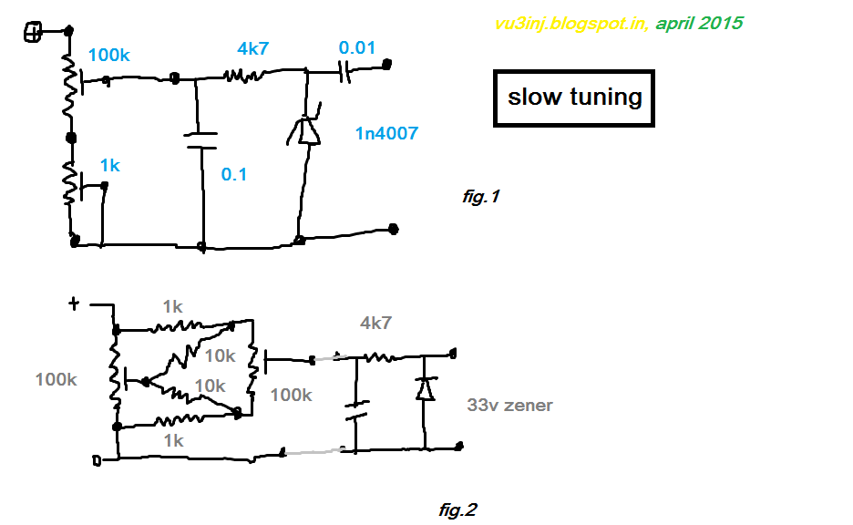
Here is the ckt diagram. As it is evolving the values are not given.

First IF amp + Crystal Filter. 10mhz.


Second IF amp+ Dector+AF pre-amp+Audio Amplifier.

If it works, i will pass it on to others..... be rest assured.....wheel is being re-invented....please wait..... till then ENJOY.....

*date 21 april 2015:- today just powered up the stages. It gives a good loud sound. Nice. also passed the click test.  oscillator and if stage brewed. Need to test it for cw note of 10mh exteranal oscillator. It should work. Lots of ham friends are looking for it. Evening hours tested it works. filter is good. feeling its little wide but will deal with it later. Now time to make the Front end.

*date 22 april 2015:- I was looking or the first mixer from my homebrew files. I have used the transistors, diodes, ta7358 et all. I wanted something simple. I was not striving for the 1micro volt sensitivity. I want something that can receive faithfully. The plain copper board finally won. I don't want to make externa oscillator. There is not time for it. I want to finish it today or tomorrow. A date to keep. A dds vfo (yes sir arduino +ebay ad9850 board to be tested). To test my own 14194kc dsb transmitter. Its time i finish the receiver as it. So decided old faithful TA7358 with its internal osicllaotr. I will not use its internal common base RF amplifier. If needed I will use the FET amp. But I think even with this simple mixer it will give good signal.

 *date 23april 2015:- I tried the TA7358AP. Put the ckt on the copper board. Put a random inductor. Not measured. It was showing 7mhz. Oh I need 4.318kc as LO. then used another coil with ferrite slug. Thus Oscillator was trial and error.  Finally taken it to the 4.3mhz mark and presto I was able to beat the TX.  Singal is low. It need to be tuned up. I feel the IF filter is very wide. It needs to be narrowed down. Now I understood what narrow and wide filter means. After putting the mixer the sensitivity gone down.. mismatch.... this might use a good RF front end amplifier. Tried to listen to the on air signal, one cw station only.... ok this thing is working. It needs final tune up and boxing... lets see I am able to get on air signal or not.

*date 24april 2015:- Now I have tuned the radio. The Local Oscilator is giving me the trouble. Reason is simple. I don't have the frequency counter. The pic needs to be re-programmed. So beating with the oscillators. So exactly don't know where its beating.  This times calls out for good RF voltmeter and Oscilloscopes.... he he... if I had that much money I might have bought the rig itself.. who does this much labour ? As test is okey its matter of time when I put it togather in a box.... wait for two three days. Then I will test it. Put the tx and see how far its able to resolve the ground wave.  Able to resolve one or two am stations with howling of carriers ( he he)

now there is nothing left.... just patching here and there front end band pass filter, boxing and error free circuit diagram and possibly the pcb.

*date---25april2015:- The problem identified. The 4mhz local oscillator is not oscillating coil was resonated with the help of one external oscillator.  Tuned it, then in the ta7358 it was not working ? reason might be the 1000pf+1000pf emmiter feedback capacitors. yes sir, it should be the problem. In my last experiments only 680pf worked. why did I forget ? I should have consulted my own notes first. I do keep the log of all my tinkering with all the comments. Its worth reading.


Here is the picure of IF strip. Its working nice. I have to re-work tweak the Local Oscillator.

If its not tamed I might use external oscillator.


*date--- 29april2015:-
One thing I observed that the  RC coupled amplifier for the IF and RF amp is good when you are using it with low gain and with xtals filters.  Good I will be using them in my designs.

I will be making the receiver once again. Still there is issued with the front end. Coil need to be wound. I will be using the old IF / RF cans.... that consumes times....  but will make it......

*date 03 may 2015:-
The input BPF is really giving me headaches. I had made the bpf atleast two ways. Missing the alladin formers. I have few RF cores but they give me high inductance. Somehow I think the receiver will come to its logical end. RF pre-amp instead of amplifying it does attenuations.....

*date 04 may 2015"- It has reached its logical end. Mixer needs to be improvised. Which will take its own sweet time. there is need of tuning up of the front end or in other words good signal conditioning is needed. The receiver is able to get 59 signal as 53 signals. Will put one RF amplifier. Then its over.
I will not publish the ckt till I make another receiver using the same components.

*date 05 may 2015:- at night time I changed the rf amplifier and presto the signal came booming. Receiver was very deaf due to the RC coupled amplifier. I needed more gain. Now audio also sounds good. But xtal filter is wide. It needs to be narrowed. The time signal is ticking in with carriers. So it needs to be tamed. I should have chosen the 11.059mhz or 4.000mhz or any If where there is no constant signal i.e... ok it works.....  BPF needs to be little modified.  Box it and use it for signal testing receiver for the experiments of dsb tx .

This receiver was worth all the effort.

The wheel has been re-invented. But first I will use it myself only. thanks guys.

xtal filter making part 3

This is the third part of xtal filter making.
After making the R7 Dayton receiver my confidence grew. This pcb was gifted by VU2UPX. Thanks charu. This whole experience opened my blocks for the filters..From lamington road I, recently  bought few 10 Mhz. xtals costing around rs300/- for 30 pieces.  How to measure ! Just see the part-1 and part-2.

srno
xtal
open
close
diff


12
24
999950
999634
316


17
2
999948
999640
308
6
ao
14
3
999957
999641
316
1
a
15
18
999953
999644
309
3
a
6
8
999965
999644
321
0


21
17
999958
999645
313
1
a
18
7
999959
999645
314
0
a
19
23
999949
999648
301
3


2
20
999955
999650
305
2
bo
8
11
999961
999651
310
1
b
22
6
999964
999651
313
0
b
5
12
999956
999653
303
2
b
20
25
999959
999653
306
0


27
22
999953
999654
299
1
c
11
10
999959
999654
305
0
c
29
27
999960
999654
306
0
c
13
16
999965
999654
311
0
c
3
21
999960
999655
305
1
c
25
14
999965
999658
307
3


9
13
999964
999661
303
3


26
26
999973
999665
308
4


7
1
999960
999666
294
1
do
10
15
999960
999670
290
4
d
4
4
999963
999670
293
0
d
24
19
999964
999670
294
0
d
16
0
999970
999673
297
3


28
28
999979
999673
306
0


23
5
999978
999680
298
7


1
9
999967
999696
271
16


Well I can get only 2 set of 4 xtals and 2 set of 3xtals. a, b, c, d denotes the selected filter. a0 denotes the oscillator.


OK. I am happy. If I have bought the 100xtals beg of KDS xtal than it might have yielded me good results.
Happy filtering.

Tuesday, April 14, 2015

On air, part-3

This is my third part for being on air. 

I had tx, I had rx. I was having problem in the QSK.  I was literally furious as I had spent lots of good money over the junks. From few good hams I bought secondhand  equipment's, and to reduce their own burden, those good man passed the buck and it stopped with me.....

I saw my own homebrew-junk-box. I was seeing that I had all types of modules. Be it modulators, demodulators, IF amp.TX amp, Linears, Power supply, Diodes mixer etc but no DDS VFO. I was finding it very hard to make it work. I am not digital-man, I am just a disecret tinkerer. Then I has realizations and I started boxing the things.

So excused myself from the  Indian Homebrewers facebook group. I was angry. I had the valid reasons. Only because you fill up some etchy-bitchy pcb with success does not mean the end of worlds. There are many things in RF world.

I dedicated my two -three days in perfecting and boxing the existing system.

I made two 20 meter antennas. Put the qsk in DC receivers and Superhet receiver. Will further improve it with tr-switching. This time the slow tuning and qsk ckt worked the miracles.

Then started the test. Many peoples helped me, coaxed me to make the dds vfo, I said the dds vfo will wait. Let me finish first what I make perefectly. And the test come ok.

Even with 2.5 to 3swr and 15 to 25watt I was able to put the signal through the south india. Then was also able to receive the control signal in my receiver. The receivers need fine tuning. Otherwise its all operational. Now final little glitches needs to be removed and it will successfully give the scheduled contacts. Sked. 14314kc.

Will upgrade to high power and dsb...

I have to thank one person for helping me out in air test, listening to me, checking with me regarding the progress...... thank you........... de vu3ink....

Sunday, April 12, 2015

VFO SLOW TUNING

now a days peoples  are using the dds vfo and all sort of digital techniques in the vfo. The days of slow vernier drive and band-spread coils etc are gone. Also there is no more production of this mechanical devices. We still love those metal gangs and slow drive !  But unfortunately we could not find them easily.... here is the todays solutions.

Now peoples use the varactor diodes. This varator diodes need to be given some DC voltage. One solution is to use the multiturn pot.

You can use the fig.1 ckt. I used it but it did not give a very clear and broad range.
Then somehow, I got hold of this ckt in PY2OHH, the Brazilian ham. In one of the VFO he used  I liked it. I am going to implement into all my vfo.

It gives a very clear and very slow drive. It can work with the 33v zener used as varactor. Earlier is used the 1n4007 as varactor. The voltage is not linearized. The two 100k pot has to be linear ( not the logarithmic) for further very slow tuning you can use a multiturn pot. How much shift it gives just enough to resolve the 5khz shift. Ok when you are using the homebrew rx/tx.

You would like to use the MV2109 etc etc varactors. Here nothing is hard and fast rule. Use whatever is on your hand.

The values of the slow tuning is given in the ckt itself.  Wire as shown in the ckt.  Don't forget where the ground is taken from ! (Will upload the fotos laters on ... ok see below )

That's it folks wheel have been re-invented successfully.
 

QSK4RECEIVERS

During one of my experiments I needed to put the QSK for my homebrew Direct Conversion Receivers. It worked. Due to diodes in front end the AM breakthrough came into the receivers.So care must be taken to manage it Don't connect it directly to the transmitting antenna. Here receiving antenna is separate from the transmitting antenna. It will work for many boat-anchors. Idea is not my original.  In my humble opinion this will work for 10 to 20watts.

All types of the receivers when used nearby needs this qsk. This saves the front and. AGC takes cares but due to this the recovery becomes fast.

I have used separate antenna. If you share the same antenna for RX & TX,,,, please ......please ....use some 100watt lamp. never use the halogen or flouroscent lamps.

During making of the receiver its advisable to Integrate the QSK into the receiver itself so that in future when you use along with transmitter you don't face the problems when I faced. Later modification is a very tedious affairs. So make the qsk when its time.

Saturday, April 11, 2015

SKCC-VU3INJ

MEMBERSHIP INFORMATTION
SKCC: 13864
Join Date: 11 Apr 2015
First Name: Indrajitsinh
Last Name: Rathod
'On Air' Name: Indra

Registered Callsigns:
Current Callsign: VU3INJ
Current City: Junagadh
Current SPC: IND
***
I have three Russian army keys found from the junk at alang ship breaking yards around 1994. I had one brass straight key, this one I could not find now.

I am trying to do daily pracitice and operate the slow cw at 14314kc. There are few takers on SSB/CW at this end of the band. So, sked works for me. My transmitter is a xtal controlled one. I use 15watt of powers. I have separate antenna and Direct Conversion Receiver for it. Its a good one and works fine. So, drop me a message on the facebook or gamail or LL and we can work the sked.

Even if we are able to exchange the RST, Call Sign I will be happy to send the QSL-Card in INDIA. or continent INDIA ( AP2,S7, LANKA).....
***

Centurion Award:No Centurion Award Status, Tribune Award:No Tribune Award Status,Senator Award:No Senator Award Status, DXC Award:No DXC Award Status,DXQ Award:No DXQ Award Status,Maple Leaf (Yellow) Award:No Maple Leaf (Yellow) Award Status,Maple Leaf (Orange) Award:No Maple Leaf (Orange) Award StatusMaple Leaf (Red) Award:No Maple Leaf (Red) Award Status
Maple Leaf (Gold) Award:No Maple Leaf (Gold) Award Status
Miles per Watt Award:No MPW Award Status,,Prefix Award:No Prefix Award Status,QRPx1 Award:,No QRPx1 Award Status
QRPx2 Award:No QRPx2 Award Status,Rag Chew Award:
No Rag Chew Award Status,WAC Award:No WAC Award Status
WAS Award:No WAS Award Status,WAS-C Award:No WAS-C Award StatusQSL Buro Status:You have No Envelopes in the QSL Buro
***
To fill up above empty scores, friends have a sked with me.
c u agn on air. de vu3inj.

ARDUINO-5

ARDUIONO & DDS VFO.
In my quest for the DDS VFO using the ebay AD9851 Module I had to wait for long years, say I first saw the dds vfo using arduino was by VU3ELR. Then somehow I could not get hold of it. The ebay module comes around rs.500/-. Then arduino chip AtMega328p comes around Rs.150/- (?). Then the16x2 LCD and Rotary Encoders. These are the hardware. And software is the Arduino which is open source.

When I started the arduino. I put the request in the homebrew forum but lots and lots heatup was generated due to some opinion difference. I said I will be excusing the group to all party to cool of and I to concentrate on my homebrew work. This dds vfo is Achilles hills for me.

Meanwhile One ham Old Man Manoj Kumar has put the dds.ino file for us in Indian Homebrewers Forum. As I was not able to compile it with LCD library. He once again graceously made the file and gave to me. A big thank you. I shameless asked for the ckt diagram. but its self explanatory in the C-code itself. Will try to upload the code here. Its a beautiful way to use the ENCODER without any special library. The credit goes to him for this code.
so

The ckt is similar to AD7C. The VU2SWX is also similar to ad7c.
Actaully all the ckt will be similar. What we have to do is this. The ad9851 modules is given the control word for synthesizing the frequency. The Arduino calculates this word by processing the rotation of the Encoder. The LCD screen is ether given the numbers by arduno to show us after necessary mathematical calculations of If off-set, SSB,CW rit etc.

To under stand the connections have a look. Although its not Atmega328.


ARDUINO-4

 DDS VFO  with ARDUINO.
The original article is being published by VU3ELR , OM SHASHI. he was one of the instrumental organizers for the Ham Fest India 2014 at Hyderabad.
Read the article published in the HFI2013 suverniours. The ino files and ckt is missing but article might inspire you.

How open source can be beautiful and smart.have a   look.

DDS VFO

Sasi – VU3ELR

A few  years ago, many  of us  faced  the problem  of constructing  a stable vfo  for  RM 96s, with limited  or no access  to calibration equipment I  had aligned my VFOs with  great  difficulty. With the lack of availability of Styroflex capacitors and NPO capacitors it has become very difficult to make a stable vfo. Being a starter, home-Brewer, I used to search the net for many alternative ideas to make a stable rock bound vfo and finally landed up with no progress as I got QRL with my professional activities.

Although QRL, I never stopped thinking of a good stable vfo that could be used with my RM- 96. I went surfing the net for various solutions and did a little work on some DDS circuits. There are number of circuits available using AD9850, AD9851, Si570..Etc controlled by PIC and other chips. All these circuits are found to be programmed using ASM, Micro C. They need some knowledge in the languages if we intend to do any minor changes to work for our applications. With little bit of working knowledge on these DDS VFOs, I finally thought of developing a DDS VFO that can be programed/modified by an average  Home-Brewer.

Like a lot of Hams, while browsing for electronics on eBay I came across some of these super inexpensive DDS modules being sold  that could be  shipped from China (for about Rs.500/-) These modules are  are far cheaper than the DDS 9850  chip which costs around Rs.1300. .  OM Paddy, VU2PEP initiated the idea and encouraged me try out a DDS with this module I had no second thought and immediately   started working on it and ordered a pair of modules and received the same in less than a weeks’ time

The Circuit:

Before embarking  on this circuit I would like to say that none of these ideas  are mine  and are  taken various references  and sources available  from  well defined circuits of pioneers in home brewing. In this circuit, I have paired my Home-Brew Arduino Uno with AD9850 module purchased online from  on EBay, a 16X2 LCD display, Rotary encoder, and a few other small parts put together making a very descent DDS VFO capable of any frequency between 1Mhz and 30Mhz.  The easiest way to manage the AD9850 is with an Arduino Uno.  A little quick work with a proto-board and I had a nice working VFO.  The schematic shown below is a little rough and I tried my best to make you understand. The circuit is a straight forward and simple  and with a little knowledge on Arduino IDE, The VFO is easy to brew  as short notice “ before you complete your Coke” you can have the up and running  HI

A word about Arduino:

Arduino is an open-source electronics prototyping platform based on flexible, easy-to-use hardware and software. It's intended for amateurs, designers, hobbyists and anyone interested in creating interactive objects or environments. Arduino can sense the environment by receiving input from a variety of sensors and can affect its surroundings by controlling lights, motors, and other actuators. The microcontroller on the board is programmed using the Arduino programming language and the Arduino development environment. Arduino projects can be stand-alone or they can communicate with software running on a computer. The boards can be Home-Brewed or purchased a preassembled and the software can be downloaded for free. The hardware reference designs are also available under an open-source license; you are free to adapt them to your needs.

If you need to know more about the Arduino platform you should check out the official site at www.arduino.cc.  I have been playing with the Arduino for only a couple of months and I already found it to be a fantastic development platform.


PCB Layout and Arduino sketch:

As the source code is unable to put on paper, the required PCB Gerber Files and the Arduino sketch is available on request via mail s4sasi@gmail.com. The low pass filter is directly taken from RM-96. The values of T1, C1 and C2 will change as per the desired operating frequency.

Acknowledgement:

I specially thank OM Paddy, VU2PEP for initiating the idea and giving me a support to complete the circuit. I would also like to thank VU2BVB, VU2CJV, and VU2ZAZ and may others for their valuable feedback and literature.

So, finally there’s no reason why you too cannot have a economical and a efficient  DDS VFO for peanuts  without slogging  and compete  with hams running commercial transceivers and work most of the digital modes which was beyond the working of a homebrewed analog vfo. This DDS VFO can be used as a plug-in replacement for the VFO many  old commercial and valve transceiver like the HW101 SB102 etc and also as useful  signal source for the bench, or as an LO for a direct conversion transceiver … the possibilities are endless!

Happy Home-Brewing.

 The wheel is borrowed from the VU3ELR. If you like it make it. All credit (and blame) goes to him.
 

Wednesday, April 8, 2015

ARDUINO-3

In this part we will discuss, what happens after you install the Arduino software from http::\arduino.cc website. Choose your system. your compute type 32bit,64bit, Linux. windows, etc, Choose latest software as it comes with more bells and whistles.

I Installed software in the c-drive. You may install in the Program folders also. There is no taboo. You may use install.exe, the complete install file. That way it will get all the required files and don't have to worry about why the usb is not being detected. I installed it from the ZIP folder as had slow net connection.

If you have installed and worked the C-compilers , you will get used this arduino console it in an hours. Arduino uses the c-languages.

Compile the example programs from the menu. As they are very simple and easy it should run. As far all ok.

Now connect the arduino in the USB port. If install was good it will be detected. In your computer go to the device manager from the control panel. Here you should see the arduino-usb. If you see the unknown device. Stop there and then.


Click on the unknown device. It will open a window. In that Go to install drive menu. You have to open the file from the driver folder from the arduino folder. There arduino uno.inf file will be there. Open it. And all is well. Now computer will install the driver itself. So you will be able to see in the control panel>. device mangager>arduino.

Now upload the blink sketch. Just monitor the bottom panel of the ardino sketch. If you see no warning and just single line message sketch size ..... bit.... than pat yolur back. You have done it.

Try to change the time loop. There increase the on off time from 1000 mili seconds to say 1000-600 and you will see the difference in the on=off pattern of the LED. This  led is on the arduino board. If needed you have to save this sketch in a different folder.

The :LED  in the arduino will be blinking it.  Now , you can be sure your ARDUINO compiler software, ARDUINO BOARD is working fine.

Thus far the wheel has been moved a little. Enjoy it.

Be care full when you take the out put from the ports to limit the current with 330ohm resistor. And not to drive any external device directly. Use the transistor, fet etc. Also make sure you don't supply more than 5volts to the board.

(Well, this part ends here.)

{ when I will make the DDS VFO from it ? I don't know. May be never. ............May be this week. I don't know.......

 As for other project ? yes sir I will make them plenty. }