Friday, December 27, 2019

Night owls net Mumbai

The year of 2019 was a very tough one for me. It was very very topsy turvey , I saw lots of up down.  Finally found the windows of 10 days at the year end. Where to go ? The great Mumbai.

Here I come to you Mumbai. It is a city which amazes me whenever I visit.  It gives me wine women and wireless the three words of bliss WWW. In my state of Gujarat due to the pitrudosham of naked old man with stick we do not get wine.  Mumbai women’s are more friendly then anything else. The inherent culture of Mumbai makes them efficient. They are equal bread winners. They work round the day.  Appreciate them. (my host)

Go to any shop and you will get desiwine.  I do not drink . But there should be freedom to do so. I love this concept of freedom.

Recently I got the BAOFENG from lovely china. It’s uhf vhf handy with 1watt or 8 watt power levels. This gave me freedom to move and make a possible call on the band . I chose the standard 145.500 MHz VHF fm . This frequently used all over the Gujarat. During my travel put the handy on the squelch mode. When AMDAVAD was coming gave a cq call. No reply . Then once again called up. There was no hope as Rajkot city did not reply my call. It was around 23.00 ist night. But suddenly the reply came. Hello 3inj de vu2mau.
I was just surprised and so much happy to hear the voice of my big guruji that was amazing . Fact is he was my first qso on vhf after many years and first on handy. I thought I got a good starting . My radio is blessed. We had a long chat . Around 15 minutes. I was on a running bus. He has a setup which enables him 35 km radius. We both were on vhf handy.  I was elated and do not know whether I spoke rationally or not. I share a special likings for adhirs family’s. In early years of my ham starting they accepted my gate-crashing. Thanks. Lastly I met SK-vu3mau at Rajkot . Feel bit sad. Ok.

I moved on .  Found the 7388 number bus which I took as a present to vu2mau. Moved on
Connected with a ham friend VU2KWJ but he was on my hometown itself to climb the mount Girnar. Took another’s friend numbers. VU2WSM .!

Then heard about the Mumbai Night owls net on 145.000 but was not able to connect. I am on 11 floor  but no way . Lost two days . Then moved to terrace. Calling a cq on 145.000 and got the reply from net control vu2pjm. The station is near the Haji Ali the highestpoint , the oldest and expensive area.

So first they were amazed to hear me . Then I made it clear it call was on vhf . I felt happy and included when they put my name on roll call. It was little hard to explain handle finally I said I am good at qrz.com . Then I asked wsm to introduce me to 2wll and 2pjm. Next day was easy for me. Then day after day I am checking in . Two more days to do it. Then back to hometown.  Hope to establish a repeater there .

73 bombay. You always give me www.


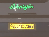
On road found a Number 7388 loved by OM Adhir, this is gift to you dear. First top most foto is my baofeng courtesy VU2RTG i recomend him. He was kind enough to put me on air. Thanks dear. Last is my QTH at mumbai. Its a tall building of Santa Crazy. i am back on my qth at gujarat on30 dec 2019.

Thursday, September 26, 2019

40 meter

I have found the 15 meter fundamental xtal. 21096 kc and 21168 kc last years my visit to lemington road. i was planning to make the 15 meter receriver / transceiver so that i can do some handy type self talk and its a nice silent band with small antenna. Started building 15 meter but ended making 40 meter ? how as I have planned the transceiver on the xtal. Now this xtal of 21168 was over tone . which fundamentally resonates on 7056kc. only component i did not check was this xtal. Everything is good as it works on 40 meter fone band.

in near future, I hope to make another one transceiver based on 21096kc which is a fundamental xtal so on 15 meter. will design a simple receiver with poliakov receiver using 10.7 MHz ceramic resonators!

Lets / Will beep the world . CQ CQ CQ DE VU3INJ VU3INJ VU3INJ K

On the Hindu holy day of dashera ( the 10 th ) day of victory, i have lighted the lamp with about 2 watt RF power on 40 meter band.

The Transceiver is based on my earlier experiment with QSK circuits. Basically it consists of three building blocks.

Part one - Transmitter chain. it consisist of keyed xtal stage. with three stage of linear amplifiers. Two stages of 2N2219 big trnsistors. One stage of IRF510 the work-horse . It works.

Part Two- Receiver section. It was earliers build. it has cascode RF front end amplifier which gives good gain. Then one stage of  TA7358AP double balanced mixer Followed by the one stage of AF amplifier & LM386 af amplifier.  The external VXO is used for receiver.

Then i implemented the QSK without switching off the RX side. This has advantage and disadvantages. From rock mite the single xtal filter is used. Diode protection is used due to strong RF at TX time.

Third Part :- is the QSK switching over. Earlier i used to make TX and RX as seperate thing but not usable due to the strong RF at tx, problem of switching of antenna change over and this prompted me to search for the suitable ckt. My primary use is CW but qsk is for SSB. needs little bit of improvision as loud thump and relay chattering is an issue.

Now lets explore the circuit on the more elaborate way.

Few Philosophical bablings.

Earlier my design philosophy was to make it reproduce-able for others. For this, i struggled to make the same ckt modules two three times to standardize. For single individual brewers,  this philosophy is not good. Make it for yourself, work it and if peoples likes it , they will implement it on their own variations. Hence forth nothing will be reproduce-able. You make your own working from my modules.

In this project I used the earlier made working modules. This reduced my making time and efforts. As the modules has been tested time and again , its lying in the junk box. Use it.

I used good quality costly glass epoxy copper board for RF stages. This solved my problems of mechanical stability, drawing circuits, etching the pcb.  I have no issue with making PCB but use whatever you have on hand.Use of copper board and small pcb island, strip cut and glued to this copper plane greatly reduce your time of making the things.  Simplicity with efficient use of the thing is motto of the day. The

i have seen that the copper board greatly reduce the stray rf problems. Use the copper board shield as seperators between two stages this will emmencely benefit the ckt in reducing the inter circuit oscillations , feed back issues.

Make a habit of using a tag for taking of AF/RF/DC connectors at the same side.

Use the sturdy mechanical boxes. I bought the commercial box for AF amplifier. It costed me around 4 -5 US dollar price ( indian ruppes 245 ) . Use boxes within the boxes. It helps solves lots of , acoustic, audio feed back and it isolates the stages. When you use the boxes for stages what happens is that you can take that boxes entirely , disconnect the connectors and can repair and replace as a unit
. The future upgrade to the ckt becomes easy and it is not cluttered.

I use lots of LED as power indicator in the individual boards / modules. This saves me lots of trouble later on as, i know whether the powers are ok at a glance.

Use of standard connectors , shielded AF wife etc greatly reduce the  complexities. you can later on wire harness it. Sometimes there are open connections., DC components, connectors possibly touching the other ground plance or other components use tube shields, plastic spacer, card-board spacers , cello tapes, insulated tapes etc. This reduces the possible component failure and increases safety.and reduces the costly repairs.

Enough babling, now lets explore the circuit modules in details.

QSK module.
I dislike the relay chattering on the CW. But this relay does two things. it has two connectors. Total 6 pins. First , it hands over the antenna and to TX stage or RX stage and second it also provides the DC voltages. This DC voltage is used as control voltage for diodes switches in the receiver front end.
I used simple back to back connected 1n4148 for reducing the RF voltages. Then used two 1N4148 diodes in on off configuration. This helps me reduce the RF going into the front end.

Xtal Filter 

Here due to BC interference and some Shortwave band strong local station i used hefty very very narrow single xtal filter configuration at last minute taken from ROCKMITE. I dislike this filter due to use of xtra xtal and its very very narrow.& lossy.  Reason is, as the rx board was made earliers there is no space left to put any xtals in the rx chain somewhere after the RF amplifier. I have observed that the two xtal filter is broad enough to accomodate about 10khz bandwidth. This reduces the noise, interference and still usable for our VXO.

Here is its dis-advantage. If you are using this ckt please make the filter after first RF amplifier. And yes use the copper board to put the xtal filter.

My earlier other ckt using vero board for xtal filter has failed. If you are using the vero board in any of your ckts please  a small copper board and put xtal filter on it. this will work.

The receiver module

Its straight forward module. You can see this described in my blog around 2018. I had made two modules. both were working. At that time used only one. The description is linked below.
It lakes AF filter. As we are using primarily CW, its advantages to use some sort of active filtering using the TLO82 , LM741 etc. I have a crude filtering in first AF amplifier stage as 150 pf feed back. And some 0.1 bypass capacitor. When you are planning use some even a single stage active filter. This will help in putting the VXO and TX xtal within 700hz of each other.

I will be putting the 10pf,1n4007 diodes for some variation of Rx freq. Every TX and RX must be somewhat frequency agile, otherwise in practical use it makes very hard.

As i have put the metal shield and module is well built, housing the big speakers of 3x5 inch size. Gives good enough sound.. This makes it stand alone module. There is no provision for external loudspeaker as well as ear-fone. As the hissing noise and normal sound is loud enough you do not need it.

There is loud sound despite the diodes and QSK ckt. You got to put limiter after the first audio amplifier. This will reduce the saturation of later AF stages.

There is no AGC or S - meter. You can use LED indicator for audio strength indications. in use i observed there are some relay clattering noice coming to AF chain and there is thumps at TX time. QSK needs some improvement. Possibly new design or i can change the 'some docile' relay at this time.

Thats is it. If i make another ckt from scratch i will implement this things for more comfort.

TX chain
It is very simple straight forward. Xtal oscilattor. the VC is used to change the freq a little bit more. here we have keyed the xtal oscillator stage.
Then there is a small RF amplifier stage. It amplifes the RF using 2N2219. i did not have any metal 2N2222 so used it. My plastic variety of 2n2222a did not work. here you can use the BC547B also. Try it, best is 2N3866 in metal pack if you can find. That transistor is a magic one but costs much more. i used RFC as load.  i used 220 ohm as emmiter load then used 110= (two 220 in parallel) this increased my RF drive. I feel need of one single stage resistive load type RF amplifier stage. As VXO drive is less. I will keep this in mind.

After that , i have used the another 2N2219 with crown heatsink. for load RFC is used but experience has shown that 25 ohm emmiter load produce too much heat and creates birdy and produces stray RF power in IRF510 stage. Needs to be cured.  Remove the RFC load and put a simple balun or ring core  broad band transformer. Use copper plate stage seperators. use  rf choke and 0.1 bypass capacitors. And increased Re from 25 ohm to 33 ohm this reduced heat but also reduce drive going to final stage.

The IRF510 stage was used with heatsink. Its standard modules. Used 7805 voltage regulator. nothing special. See, the fotograph. it has to be mechanically strudy and isolated. No VCC/dc-hot part should touch ground or other components. It does not heatup much. The heat sink is enough for it.

The mechanical Boxes.
This is not part of any ckt but , this is very important how your devices functions and gives comfort to you in real time. i have used standard connectors. by using and housing the ckt modules in seperate boxes on board the holes to be drilled to the chesis is reduces. This helps later on in house keeping.

Boxes needs to be well ventilated for tx chain. Only heat sensitive component here is the second driving transistor. So, will be putting fan. When i first put the big fan it produced  stray RF & noice in RX chain . This is not tolerable. So, it needs to be changed. later on i will put another fan without producing any RF noice. So, take care that your FAN is not too much vibrating and producing the RF noice in DC receiver. Fan is needed but noice of rf can not be tolerated.

As i am not using the transmission / on air, so the dummy load is connected at Relay on tx pin. So lamp is connected but on on the receiver antenna. he he ? clever one. Later on will remove this lamp and RF will directly go to the antenna.

Calling CQ
i have Russian morce keys. Its very hard to use this straight hand key constantly for just calling cq. hope to make a CQ caller using Arduino ckt board. with it even beacon can be implemented.

Why i made this ckt.

A week ago,some advertizement of cheap bitx was going on facebook. i asked the seller to provide me one but made a condition that you check and rechek before shipping it to me. He declined and i felt from their reply a bit abused. So, that to prove them that i can make things, i brewed this ckt.
I  lack the plain simple DDS VFO technology. If somehow i can have this digital things my life can be easy. But, anyway thanks for challenging my capabilities you and your tech are use-less to me.However you might be big & naughty but you lack compassion and vision to see that someone also deserves the good things despite whatever their graha, religious, political views.

What now ???  have few QSO & QRM on 7056kc. 
(as of i am modifying it to the 7159 & 7056 cw and then to the DSB for the local reg chew with a friend or self talk - a mad ham).
The Wheel has been re-invented. Enjoy.

Thursday, September 19, 2019

Micro BITX

I personally do not like the bitx I have . I have two PCB boards lying around but I am not making anything. The success marketing & manufacturing of bitx is due to the components placements done
In a more simple way .

The maker of the bitx has solved many headaches for this rig but there are many issues which are hidden and it is not easy for the novice builders to make this rig without the some expensive tools. If it was so much easy to make why peoples did not make it enmass from the pcb given at a hamfest. it contained the fault and there was no rectifications. This rig is not for the building. If someone builds and its operational use it. the maker of it lakes the heart .?

yes, bitx suks.

Monday, September 2, 2019

Direct Conversion receiver : all transistor.

I wanted to experiment with 3 transistor CA 3028a cascode amplifier.PA2OHH & VU2ATN did decades ago. But, could not find 8 pin ca3028a ic from junk box. yeah. Yesterday was a rainy lousy days. Mostly holiday so did not wanted to waste searching junk boxes .

What to  do ?  Implement ca3028a differential amplifier with transistor. On hand, I had bunch of BC 557b lying around. Took a vero-board and started placing the components.

I had rough idea of circuit. Drew the circuit. Then Redraw it. Put the components. Still not sure if exact values but it was evolving rapidly.

What i mean by component placing on veroboard ? When i build the circuit from scratch, i usually place components on verobaord. Arrange and re-arrange as per my likings. Where components leads are shorter, where is access to ground-bus and Vcc-rail. how it can be neat. there should be minimum jumpers etc. I place the component and let it stay over night. And on next day i change it add something which i missed and then finally solder.

When you are making transmitter then always start with oscillator stage and proceed to final RF amlpifiers. When you are making receiver then start with Loudspeakers, Af amplifier stage then  detector and RF front end, mixers etc.

I started building AF stage but immediately stuck at components values of TDA2822m based audio amplifier circuit . Searched net and finally it was found in my blog itself. Next day soldered this audio stage. Did not work. Then again changed audio IC.  Then reheated all joints. Now a slight click came but not working satisfactorily. Made AF pre-amp. No audio. Removed the audio jack pins and directly used open wire . Finally it worked. It was some loose connection somewhere. It needed to be re-heated for dry joints etc.

Soldered the diff amp using the transistors. This is a product detector. I never tried differential amplifier as product detector. This was first experiments. To me 4 diode ring modules gave me consistent results. This Diff Amp Passed the hiss-noise test. The bias resistance network was placed at i/p transistor. Corrected the mistake and placed it at the o/p transistor - a Common Base stage. Because i/p is CE and o/p is CB . Passed the noise test. Then place the input RF amplifier. But did not solder as the put put motor-boating was came. I was using 9 volts battery.

Now its time to make xtal oscillator. Osc made with bc547 stage. why bc547b it was available , i used up all bc557 transistors. he he.

Now . Made RF amp finally. i thinking of using a  single transistor bc557b RF amp or cascode RF amp using two bc557b. Then preferred cascode. Still thinking, what to use as the RF load ? RF-Transformer, RFC ? these are reactive loads.  I said let’s start with pure Resistance for a test.

RF amplifier Worked but that annoying put put noise ??? Then as a after thought removed the 9 volts battery and used real 12 volts psu. It works wonderfully. No put put. ohh it seems the battery was weak. Now, Finger test gave me roaring noise. Without it it’s almost silence.That means it has enough gains and its low noise. I used RF gain control preset and that showed me how smooth this stage is.  Good.

Need to put into a proper box. its my experience only projects has lasted which were either boxed or carefully wrapped into a container for future use. Hope to box it.


I made something after a long time. It needs no further developing. Its a little circuit usable for the demos. Make a single transistor Cw tx and use it as a demo receiver or use it as  CWTX tone test receiver tool.

Thats it. we have re-invented wheel. Lets use it as it is.

Sunday, September 1, 2019

SLA battery recharge

My SLA battery was idle for a year. So tried to recharge it. Failed !
I used rain water string to top up the water. First used 12 volts to charge it.  It charged a bit from flat to 1 volt.
Then I used 36 volts transformer. It charged up to 6.6 volts (3 cells) so it was half capacity. 2.2 volts . Next day it get discharged. So one day I let full 36 volt on a single cells. Reached 3.3 volts in three four hours.
Next day it got once again less then 2 volts. Tried to charge again and suddenly my transformer got burned ? Due to heat internal insulation got eroded. WTF . Dumped it.
Moral is do not let your battery get discharged for long. 

Sunday, March 17, 2019

DDS VFO WTF

I had the dds vfo gifted by my ELMER OM VU2DEV, Dev garu.


At present it’s non use as I want to use it in DC RX but it’s for super het. Let’s hope to use it as it is. 

Thursday, February 7, 2019

Balun for wire antenna

making balun for wire antenna. I wanted to make EFHW.  I want to make delta loop. Wait !!! My time resources are limited.  I said what I have ? Toroid -No. but MW Ferrite road yes. Made balun.


Here is the schematics.
That might work. Hope so.
as of  22 may 2020 there is wire antenna working. do not have swr meter but i think it works.

Wednesday, January 16, 2019

SLA batery charging

SLA battery charging.

I have few batery lying in the shelf. Not charged. Its sealed lead acid battery. that means its sealed. its miniversion of car vehicle batery. Generally 4 vollts are standard. So i have 500 ma - small batery, 1 amp and 2 amp batery. All just not charged , deep discharged.The previous usage experience is that i have to regularly charge it. But, could not find the commercial charger circuit.

There is very strange theories as we have used this batery system 100 years.Ohh baghdad battery ? Anyway i will be makinhg a simple charger circuit and one is fully charged then will constantly tripple charge it.
For amazement look at the battery which might have used for GOLD-electoplating the Egyptian idols and possible to light up lamps.
baghdad batery

baghdad batery


Have a look at the baghdad battery.


And i opened my SLA batery.

Need to get the distilled water and a syringe to fill it up. You have to reverse connect it. Then fast charge it. Trickle charge it. And use it and recharge it.

2. Cover opened
1.SLA batery

3. Bottle opened
I have to buy the distilled water or use the rain water. yes, i have plenty of rain water. i collect it during rainy season and keep it in bottle for a year long use to worhip my gods idols.  Water tastes good.
Today is 19/August/2019.
I saw a vedeo where a person was rejuvenated the big SLA battery with  rain water and a professional charger. Used syringes. Topped water. About two injections it needed.
Anyways. I do not have charger , so I did use my bench power source and gave 12v directly to this battery. It measured 0.2 volt a very bad condition. But I knew it needed water . It was charging and suddenly I hear a pop up sound . I looked but There was nothing . Transformer was hot ! Battery was hot. Then after some time measured the battery voltage . It was 2.2 volts. then show that seal was open and water was bubbling! Ok due to gas pressure it opened. Then , found it removed other rubber cap. Let it charge. It’s heat intensive process so use fan ! Once it’s workinb is tested will let you know. 

Sunday, January 13, 2019

Silent key

every radio station when closing down calls for last message anyone waiting any last message. Station vu3inj calls for this.  From now on everything should be taken as  SK.
Life is beautifully ful 

Sunday, January 6, 2019

7159kc trx qsk

I had a rough time understanding and choosing a proper qsk for my TX and receivers. If you see my early post you will see that I used different modules to make Transmitter and Receiver

In this transceiver i tried to implement TX and RX chain in a single BOX. My results are very satisfactory. So, lets hear the success story of QSK.

By the way For this TRX Next step is to make a cw band xtal VXO of 7000kc (This xtals were given by my friend Arya ) , and 7159kc DSB TX.  Need of VXO is apparent. A single stage af filter is also good. But let me first put it on air with just 10 foot high about 50 feet long wire. It works. Years of homebrewing has told me to make a solid brew. Put your modules firmly , in  a box, shield them. use decoupling , use plenty of space. Make modules and make it in small steps. Test it and see that it works.
Filter 40 meter

Qsk

Filter


Yes wheel is reinvented and revised.
I have put the few fotographs here and will write more about it.

1. You need a Relay DPDT (8 pin relay) , a must to change over the Antenna and Generate control Vcc  ie. RxV, TxV.

2. Transistors can be used to switch few modules. (will describe later on). For SSB single relay will work but for CW you need more control mechanism. Or use a relay and manually switch TX RX on off, clumsy.

3. You also need Diode 1N4148 switching for protecting the front end of RF Amplifiers. I implimented the M0DGQ as given in the SPRAT magazine. picture given below. Here if there is no control voltage switch protects our front end. This switching always introduces some signal loss . but ok with good dipole external antennas.

4. You should use "10k+LED" for indication of Vcc, On-Off,TX,RX, etc. This indication helps in quick visual  fault finding or working of the stage. It helps a lot during the development stage. If current consumption is an issue then later on remove it.

5.I will be listing all the switches usage. Relay, Diode, NE555, 1N4148, BC548,1N4007.


QSK

TRansceiver

VK3YE 

It has RF amp, Ground switch 
and Control voltage

Another QSK


VK#YE VXO