
I wanted to experiment with 3 transistor CA 3028a cascode amplifier.PA2OHH & VU2ATN did decades ago. But, could not find 8 pin ca3028a ic from junk box. yeah. Yesterday was a rainy lousy days. Mostly holiday so did not wanted to waste searching junk boxes .
 What to do ? Implement ca3028a differential amplifier with transistor. On hand, I had bunch of BC 557b lying around. Took a vero-board and started placing the components.
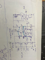
I had rough idea of circuit. Drew the circuit. Then Redraw it. Put the components. Still not sure if exact values but it was evolving rapidly.
What i mean by component placing on veroboard ? When i build the circuit from scratch, i usually place components on verobaord. Arrange and re-arrange as per my likings. Where components leads are shorter, where is access to ground-bus and Vcc-rail. how it can be neat. there should be minimum jumpers etc. I place the component and let it stay over night. And on next day i change it add something which i missed and then finally solder.
When you are making transmitter then always start with oscillator stage and proceed to final RF amlpifiers. When you are making receiver then start with Loudspeakers, Af amplifier stage then detector and RF front end, mixers etc.
I started building AF stage but immediately stuck at components values of TDA2822m based audio amplifier circuit . Searched net and finally it was found in my blog itself. Next day soldered this audio stage. Did not work. Then again changed audio IC. Then reheated all joints. Now a slight click came but not working satisfactorily. Made AF pre-amp. No audio. Removed the audio jack pins and directly used open wire . Finally it worked. It was some loose connection somewhere. It needed to be re-heated for dry joints etc.
 Soldered the diff amp using the transistors. This is a product detector. I never tried differential amplifier as product detector. This was first experiments. To me 4 diode ring modules gave me consistent results. This Diff Amp Passed the hiss-noise test. The bias resistance network was placed at i/p transistor. Corrected the mistake and placed it at the o/p transistor - a Common Base stage. Because i/p is CE and o/p is CB . Passed the noise test. Then place the input RF amplifier. But did not solder as the put put motor-boating was came. I was using 9 volts battery.
Now its time to make xtal oscillator. Osc made with bc547 stage. why bc547b it was available , i used up all bc557 transistors. he he.
Now . Made RF amp finally. i thinking of using a single transistor bc557b RF amp or cascode RF amp using two bc557b. Then preferred cascode. Still thinking, what to use as the RF load ? RF-Transformer, RFC ? these are reactive loads. I said let’s start with pure Resistance for a test.
RF amplifier Worked but that annoying put put noise ??? Then as a after thought removed the 9 volts battery and used real 12 volts psu. It works wonderfully. No put put. ohh it seems the battery was weak. Now, Finger test gave me roaring noise. Without it it’s almost silence.That means it has enough gains and its low noise. I used RF gain control preset and that showed me how smooth this stage is. Good.
Need to put into a proper box. its my experience only projects has lasted which were either boxed or carefully wrapped into a container for future use. Hope to box it.

I made something after a long time. It needs no further developing. Its a little circuit usable for the demos. Make a single transistor Cw tx and use it as a demo receiver or use it as CWTX tone test receiver tool.

Thats it. we have re-invented wheel. Lets use it as it is.
 What to do ? Implement ca3028a differential amplifier with transistor. On hand, I had bunch of BC 557b lying around. Took a vero-board and started placing the components.
I had rough idea of circuit. Drew the circuit. Then Redraw it. Put the components. Still not sure if exact values but it was evolving rapidly.
What i mean by component placing on veroboard ? When i build the circuit from scratch, i usually place components on verobaord. Arrange and re-arrange as per my likings. Where components leads are shorter, where is access to ground-bus and Vcc-rail. how it can be neat. there should be minimum jumpers etc. I place the component and let it stay over night. And on next day i change it add something which i missed and then finally solder.
When you are making transmitter then always start with oscillator stage and proceed to final RF amlpifiers. When you are making receiver then start with Loudspeakers, Af amplifier stage then detector and RF front end, mixers etc.
I started building AF stage but immediately stuck at components values of TDA2822m based audio amplifier circuit . Searched net and finally it was found in my blog itself. Next day soldered this audio stage. Did not work. Then again changed audio IC. Then reheated all joints. Now a slight click came but not working satisfactorily. Made AF pre-amp. No audio. Removed the audio jack pins and directly used open wire . Finally it worked. It was some loose connection somewhere. It needed to be re-heated for dry joints etc.

Now its time to make xtal oscillator. Osc made with bc547 stage. why bc547b it was available , i used up all bc557 transistors. he he.
Now . Made RF amp finally. i thinking of using a single transistor bc557b RF amp or cascode RF amp using two bc557b. Then preferred cascode. Still thinking, what to use as the RF load ? RF-Transformer, RFC ? these are reactive loads. I said let’s start with pure Resistance for a test.
RF amplifier Worked but that annoying put put noise ??? Then as a after thought removed the 9 volts battery and used real 12 volts psu. It works wonderfully. No put put. ohh it seems the battery was weak. Now, Finger test gave me roaring noise. Without it it’s almost silence.That means it has enough gains and its low noise. I used RF gain control preset and that showed me how smooth this stage is. Good.
Need to put into a proper box. its my experience only projects has lasted which were either boxed or carefully wrapped into a container for future use. Hope to box it.


I made something after a long time. It needs no further developing. Its a little circuit usable for the demos. Make a single transistor Cw tx and use it as a demo receiver or use it as CWTX tone test receiver tool.

Thats it. we have re-invented wheel. Lets use it as it is.
No comments:
Post a Comment