Thursday, March 20, 2014

RA3AAE detector

 ra3aae
ra3aae subharmonics detector


DIRECT CONVERSION RECEIVERS.

when making the 14316kc cw and dsb transmitters one receiver was needed for monitoring the local signals. i have tried few projects with the direct conversion receivers.  I had tried successfully the ring diode mixers but now a days dont have the ferrites. What a problem.  due to this despite the  caution of a good brewer (VU2ESE). I tried the ic based receiver.He suggested to use DC-40 receiver (ARRL origin) and re-produced world over.

 TA7358AP. a 9PIN sil package fm front end ic as used by py2ohh   it worked but there was problem heavy am breakthroug could work as the local monitor but  junked it. later on i found that py2ohh also used it as building block for his rigs IF stage. i should have taken the words of OM very seriously.

This TA7358 will work within the superhet receiver  as a second detector very fabulously. This ic also gives good performance as the mixers, frequency converters and A very very good DSB modulators. So, i love this ic but not worth for a dc receiver.

So, back again looking for a good receiver to monitor all the signal from homebrew transmitters. LRR40 never worked. My main SAIT Marine is failing me on 40 meter in fact less than 10mhz it is becoming insensitive.a serious problem. I was upset.

Then as a last try, there were two options 1.to work with the digital switches (4066) or 2. these un-conventional looking diode sub-harmonics detecktor. infact russian hams are very fond of this detectors.

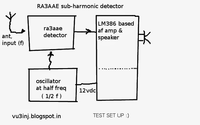
RA3AAE sub-harmonics detector


saw few ckts on net but finally decided to go with PA2OHH ( HE IS DIFFERENT FROM A BRAZINLIAN HAM-PY2OHH. PY2OHH has made  the ararinha). This european hams has done a good work on this sub-harmonics detector. he has extensively used it in his rigs. 

back-side of pd
You would not beleive that, withing 10 minutes of the brewing it started working. I did not expected the performance to be so good. so i will stay with this detectors.

beauty is that for 40 meter your oscillator needs to be on 80 meter. i can make the 80 meter oscillator using the ceramic resonators. it has  half the signal frequency. so can be used as QSK signal monitor. will develope it further to a fullfledged receiver for 40 meter.  
CLOSE UP VIEW RA3AAE DETECTOR

Working test :-

For af amplifications a lm386 bases complete audio amp box was used. (see singal tracer post). a small 1 meter wire was used a s antenna.

test set up
 from left, wire-antenna,(tuned ckt is back of first board), ra3aae detector, oscillator. in the back-ground sketches of the the various ckt using this detektor.


test-setup


I dont understand the preset (p1) but when put into the exact half position quality of sound is okey , volume is low. May be it is used to balance-cancel the AM breakthrough....


How to choose diodes:-

there was no guidelines. but, i understand that it is a balanced ckt so, measured the 1n4148 diodes forward resitance in the digital multimeter in 2k range. the two diodes which gave me the same reading were choosed.may be one or two ohm difference will work !

Circuit ( presently used as on 22march2014):- 

my ra3aae experimenta ckt
I am using this ckt. But would like to go for a commond base rf input amp and an common base AF AMP. the hiss of common emmiter in af amp stage is untolerable. My purpose of listening to the cw beacons is solved. so, its okey for me. will box it and if i make further refinements will inform. there need to taken care of the low impedance. p1 has to be low 220 ohm .... when i connected it with big antenna there was problem of complete am blanket so i have to redisign and make a good rf front end taking above issues.

CONCLUSION

:: THIS DETECTOR CIRCUIT WORKS ::
 

Further:-

there are lots of the pair of xtals available ie. (24mhz-12mhz), (20mhz-10mhz,) (10mhz&5mhz),  ( 8.866 mhz & 4.433 mhz) etc. so they can be used to test this detector and possibly use it in some-way or others. these detectors are better than other diode detectors in practical use. try it yourself !

Please dont use it as the front end mixer. I have never encountered ckt for using it as the frequency changer. However, it works good as the product detector. why ? i dont know. It requires very low oscillator power In fact there is needs to reduce the power. I tried to put lesser value capacitor for taking the output from the oscillators. I have not heard the 40 meter signal on air as i am using it as a very simple signal monitor receiver for vwn tx on 40 meter. will update more if i find up anything useful...  (19march2014)

This is one of my project which was realized within half hours including all the r&d. I am surprized why in VU, hams are not using this ckt ? i dont find any problem with it.
Reading sources:- 

I have taken the help of two sites.

First is above mentioned PA2OHH. for  taking the design. further-

Second helpful reading is the http:// www.ke3ij.com /  please aslo visit it. there is a beautiful explanations and his own experiments is shown. worth see his site.

g3bxm has used it in WSPR applications. worth to see his blog also. Roger G3XBM's Amateur Radio Blog:  Roger G3XBM's Amateur Radio Blog:


thats is folk. use this strange wheel. it was always there. but we were not beleiving it....

Thursday, March 6, 2014

on air


this is the third part of rm96 tranmitter:- 


Now every module is individually tested and it is time to match/ interface to each other and to be on air. Till today we have reached from dsb exciter , power supply to a small 1watt linear and then big linear stage.

Linear is readymade( homebrew) and it will be driven from dsb exciter. This linear likes the 50 ohm 1watt rf. But, homemade dsb exciter produce anywhere 2 to 5 watt RF. The ham who built this linear cautioned- not to over drive and use it with only 12volts at and not 24volts/36 volts as there will to too much power. I understood his caution. With simple dipole even with 10 to 20watts this tx will be heard all over the india.
Now my quest to be on has put me near to  the antenna and it will ultimately to your qth via ether:-

Attenuator, 3db pads:-
attenutor pad

By using this db pads, we are sure that input output impedance will 50ohms. Will save lots of headaches.

db pads, attenuator pads are the passive parts. it takes the rf and attenuates/reduces its power and pass on to other stage. they are bidirectional can be used anyway. In the web you will find online pad calculators. These are two types of pads or attenuator. One is PI- type and another is T-type. There is standard resistance values available in various tolerance, power ratings and materials. Use only carbon filament resistors. Generally they are available in less than 2watt range. No need to use high tolrance say 1%,5%. In our simple work even 10% will work, measure it with DMM. Choose the resistor with value as close as possible. Dont use wire-wound resistors. To see what material is inside the resistor,scrape one resistor's outer enamel. In the carbon resitor it will be black and if there is any wound components,anything spiral,metals discard it.
i will use the values given in J.A.G.A.W.A.N.A  blog. It is a very nice but albeit in the malay... hope he will publish it in english. He has done very good experiments and also put the clear ckts and fotos. eye candy. it is a worth to see this blog. Anyway for your db needs various online calculator are available to calculate the resistance and db values. google it......

faults of voltage regulators:-

In four different instances my voltage regulator ic have faulted. two were lm7812 became 5volts due to accidentally shorting of pins during testing some ckts. For a very brief periods these ic tolerates but it was a very real short. So, it produced only 5volts and i have to replace them. In bitx receiver input was accidentally shorted and the LM317T went bust. It happened two times. First fault has no cure unless some current limiting ckt is made or fuse is placed so that damage become minimum. For second fault there is a cure. Input short happens when there is dc voltage is on output but there is no dc voltage in input so a 1n4007 diode can be place from output(anode) to input (kethod) and problem solved. But, it cost me 4 ic. LM317t is little hard to find in my city. So, imported from metro. I think in the bitx design there should be this diode. But, anyway there were not expecting this fault as power transformer is alway connected. But, i am using the bitx-rx as qsk with my dsb tx.

Bitx- utilising only receiver portion boxed it.

bitx in a box.
I am putting this bitx into the box after a year. I got it last year. It has frequency readout and tx (not working). It gives me a very clean and clear signals. I like this for its audio quality. The homebrewer friend has really worked hard to make the xtal filter, but anyway one of the days will make me another bitx. My thanks in advance for making me a bitx. I am going slow but i have no other options. I am not keeping my date to be on air, but there are some factors which i can't help.

Another friend has promised me few xtals in the crowded section of the band i.e 14150 to 14200kc. I am waiting for these xtals otherwise people have to stretch themselves to give me a curtsey single contact. 14316kc is a way too off from the crowd. I am thanking in advance for all the friend sfor trying to be with me on 14316kc. But, after initial success ,will sure make someways to come near to the crowd from the corner.

Now is the hard test to connect the power supply switches, antenna switching and antenna with the daemon of vswr to be tamed without vswr meter.

I have waited for long long time to be on air, atleast i can wait for few more days either to say hello day after day or say finale QRT after spending lots of money.

When the Bitx was put there were few glitches i.e due to the short needed to replace the power supply ic lm317t. Then added a fuse, switch. But, audio power is little low ! boxing effect ? Marked its reading 4.272.6kc of LO freq. It means for 14.318 input signal on counter shows the 4.272kc there is constant difference of around 44kc.LO should read 4316kc. Its okey. Now, dsb-tx also tested with a dummy load and quarter wave ariel. Made final adjustment.  Put the attenuator pad power decreased but amp is stable.  I dont want more power.1watt will be nice to drive a linear.

Now time to test the linear.  Tweak the existing dipole. Then get a  SWL date from Jamanagar city, Rajkot city, bhavanagar city or from north/south , then try two way to declare either failure (QRT) or success. (QSL). LETS SEE.......

Why xtal in the age of digital electronics. I have tried lots of configurations with failure now i want to be on air quickly that's reason using the xtal tx.

09March2014:-

Today is sunday wanted to make tx running but there was one problem, how to solve the over current problem.read up existing files in my collections. Hummm overcurrent can ruin the dream withing a minute. So, something to protect from over current ? Found answer in the SimpleCheapPA.html.  by AC2CZ/VE2 . the current sence ckt. I will modify it and re-draw the ckt.


It basically measure the current and when it exceeds (3amp), the LM7805 regulator is switched off by T1. Power to linear is cut-off and thus the linear is saved from the open-short vswr conditions.

So, the regulator also has to be little thin i.e. No, electrolytic capacitor otherwise it will create the problem as depicted above.

10March2014:-

bitx-audio problem solved in the input pins there was a very thin stray wire shorting the input. It seems when you box all short of troubles comes forward.
current sense ckt

I ported the current sence ckt to the bc547,bc557 type common transistor as there is less current intake by these devices. Will test it today. In this also gave the resistor calculations for the  current from which the controlling starts.
For 3amp r is 0.2 ohm ,a real challenge to find it but with combo of 1.1it can be realized. 5 resistor in parallel.

11march2011 :-
0.27r a fused variety is a good one. dont use carbon resistors. modules ok. when all is okey LED LIGHTS and there is 5volt, when vcc is shorted the 5volts drops to near zero volts. this only protects the linear amp but not preventing , cutting off the shorts.

dummy load


Made a dummy load from 11 resistors each having the 560ohm resistance. 3watt carbon film variety. so load ready. It become 33watts.

12march2014 :-
I bought the computer fan. It is a fan which is placed on the computer body to force the outer air into the chasis of the computer. There is another variety of fans which is used on the CPU heatsink.

Tested the configurations. applied rf to the linear. i was hoping that there will be heat and loud noice in the nearby receiver which is placed at 25 foot far and its antenna is outside the home about 30feet away from the tx.

It was noticed that the heatsink is not becoming hot. switched off the fan. no way its cool. irf510 is a very very nasty devices. it can't be cool. so, its a problem.

removed the 3db pad. it increased the output signal in radio. connected the simple 1/4 wire.  with only tx and with linear the audio is same.....humm that means it is not amplifying at all. tried different power supply. one thing noticed the current remained same about 30 to 50 and not peaking up sympathetically with voice.

At last opened up the linear  box and presto there was the culprit. the input  BNC connector was  very loose so it was moving freely and due to that no input to the gate was reaching. so, this was the real culprit. it ruined my 2 hours preparations, my one trip to the shop and all. This coaxial wire is very thin.  Now, have to solder the coax to bnc and try again tommorow. t

13 march2014 :- Tested the linear. there is some glitch. I am not able to get it hot. there is vcc and proper bias ckt. rf drive seems is okey but not producing the rf power. hmm... where i don;t understand ? I could not find any faults ! so, waiting for the Expert advice, fone a friend option.

If this does not work, for a long time i am going to be QRT. I will not invest more money, time and energy. I have already invested the more than a rigs price over the two years. Lets pray it works as designed. i think by seeing  my frustrations other hams might also get dis-interested and loss the faith in homebrewing. but faith of friends is keep me going on.

This evening i had interesting QSO on facebook.  One was short and one was long long. thanks guys.

Thanks vu2yfd i will not quit. i have never quitted . Fact is i am a lonely ham. within 100km radious no one is there to hear even my VHF signals. Now, south indian hams understand how lucky they are, that within 100km there are lots of active hams on hf (40,20) and vhf.


arrl linear as used in RM96 which
is used to drive a push pull amp.
Main problem is, tech is there but not sharing as it looks trivial. once again fired it. with miracles its becoming hot and dummy load is also heating up. but i think it is self oscillations. tried different exiceters. i have cw tx, dsb tx and one arrl rm96 in the box. Only on audio tone it gives some output but on voice modulations rf is low. so still needs to do some tweaking and waiting for reply.


With this rm96 , 3stage linear amp i am driving the push-pull amp based on the IRF510.

PP amp takes the 1.28A at about 36volts. Heat sink needs the fan. fan takes 12 @210ma. dummy load also becomes hot which means there is some sort of rf energy coming out of the pp linear.

Another friend has a similar linear. He says it takes the peak 2amp at 24volts dc (a regulated voltage) and takes very low current during the idle. Hmmmm . Sure sign of self oscillations.  I will cure it. I know the fact that the ham who builds this linear is a very reliable person and good at his work. Please do buy from him. He has good linear pcb, know-hows and proper toroids sets in VU land.


If out of 100 only 5 does not work then may be i have the 5th. This means i need to do some exorcism to cure the ghost of murphy to be on air.
(I have to let my friend use my home-brew boxes lying ilde over years ! what else by exorcism you mean ? )


problem
(as of 15march found out that innoncent looking co-axial cable connecting from rf transformer to the output BNC connector's connections were swapped so its braid was acting as a load and causing so much trouble. how did i figured out please dont ask. it was found after i promised to let use my boxes. he he he. How much power this linear puts i have not measured so dont know yet.

PROBLEM SOLVED RF PUSH-PULL AMP WORKS AS DESIGNED  )

14march2014 on the coming sundays will fire it again for on air test.will use the dipole on 20 meter and with xtals- freq 14331kc, modulated tone (audio tone given to the modulator instead of voice) if other hams around 150km says ok then will try to modify / rectify further otherwise it is QRT.This much near and still not there. it happens its the  RF. (roough)

I dont think i have to further add to this page. Ya, i will not modify it except few errors and if any r&d is done it will be posted on the rf amplifier page.
Any input from friends are welcome.
**************************************************************************
addendum

17march2014 Reply came with more informations. thanks OM. It seems i have given him sleepless night also. My apologies. It was not your fault nor  mine, just it was the murphy behind me. I am restoring my first made superhet and tweaking-up to give it a new QTH.

Now i have to make it work on air. and move to 14194kc using the 10M and 4.194 Mhz xtals first dsb then ssb. later on i plan to use a vfo of 4000 to 4500kc  to cover entire band.
( as of 27 jan made the DSB modulator for 14.195kc,, see the blog )

thats it folks ! i have not invented/re-inveted the wheel.  If you can make it work then wheel is yours.

Homebrew RF Power Amplifier

Thank god i have reached to this point after having the real linear amplifier.

I am going to edit and re-edit this page for sometime till i make a linear myself.


vu2ptr_linear
At present trying to use the linear made by vu2ptr to increase my ham radio life and to be on air urgently.

Later on i will make another linear  of this or any other design (push-pull or single ended FET)  and put the process here. ,

If anyone wants to buy ready made linear or its pcb, toroids etc please do contact vu2ptr directly. He also makes vswr meter, lc meter , frequency counter etc.


Making linear:-

RF amplifier design:-
Now, organizing the available info for use. It becomes very hard to choose from, but generally all are derivative of the wa2eby irf 510 push pull linear amp design.

Toroids, FETs & other things.

On hardware front I have toroids, irf840,irf510, power supplies, dummy loads so that is not the issue.

But will take time to first pack my existing things and put into the boxes. thats priority...........

The single ended linear:-
Most probably i will start building the singe ended IRF510 based linear. It will same as the done before but with more power and more current and proper toroids. I think air core toroids does not drive the other stages properly due to some reasons. Don't use the air-core toroids in the power amplifier. simple ferrite cores (slugs) can be used upto the 1watt.

when in doubt where we turn for help ? THE ORIGINAL OEM

HERE IS WHAT vu2RM HAS TO SAY. (My- copy- cut- paste- tech)

PUSH-PULL AMPLIFIER FOR 14 MHz
By: S. Rama Mohan Rao, VU2RM

    After working many years on my RM-96 with IRF830...etc. in the final PA, I have tried the same tried the same circuit for 14 MHz transceiver. The same broad band is used with IRF830. It has given an output of 4watts or so. Then, I have gone deep into the subject of VMOS & TMOS power FET's. I have decided to use these devices with Low CISS & COSS (input & output capacitance) values. I have finally chosen to use IRF510 devices. This has a maximum Voltage (VDS) of 110 V.

I have built a push-pull stage because of the following reasons:

*      When a tuned circuit is used in the final tank circuit with a single stage amplifier, the quality of the signal sounds good.
  *
      Nevertheless, with a single stage broad band it is not the same quality.
*

      I felt that this difference is due to the flywheel effect of the tuned circuit.
    *

      During the technical discussions with some of the home brewers, it is learnt that the)/also found the same when the wave shape was seen on the oscilloscope.
    *

      The positive and the negative half cycles are not the same
    *

      Therefore, I have decided to make a push-pull amplifier.
    *

      Also for the reason that as we are using broad band amplifier, there are bound to be some harmonic generations, due core saturation of the final toroid and various reasons.
    *

      In push-pull these can be avoided largely and therefore less spurious outputs and better quality.
    *

      Keeping in view al/these points the following circuit is evolved and it is working satisfactorily. 

Experimentation made on this circuit:

    After building this circuit, I found, one IRF is getting hotter than the other. I made all checks I know, but it is observed that one gate is getting more voltage than the other. Then I reversed the secondary windings. Now, the other gets more heated. So evidently, IRF has nothing to do with this unequal drive voltages to the gate. I tried it with an imported toroid. No luck got fed up and thought of introducing negative feedback to equalizes the gain of each FET. So, tried combination of RC network, which is a general practice. About 100 Kilo ohms in series with 150pf capacitance from drain to gate. Now both the positive hail cycles and negative half cycles are equaled and the defect of one FET getting hotter than the other vanished. The quality also improved. Even I operated for one or two hours the heat sink is not getting heated up. i am using 22 Volts supply on the drain and it draws about 2 Amps. (i.e. 44 watt DC input). It is giving a power output of 25 watts into a 50 ohms antenna as measured on a Daiwa power/SWR meter. Further, there is no reflected power from the PA stage. So, RF filters are not used.

    I have not built a 21 MHz RM-96, but looking at CISS value of IRF510, I have a strong belief that it can work on 21 MHz also. So this will be a good choice for 7/14/21 MHz power amplifier. When one Ham from North India told me that he is using IRF840 in 14 MHz and is getting about 20 watts output, I immediately got hold of IRF840 and replaced the IRF510 with IRF840. The power output is just 4 watts. I have increased the voltage from 22 V to 40 V, the output power went upto 10 watts. However, the heat sink is getting hot indicating that the efficiency is Low. Therefore, I left the PA like that, settling with IRF510 only. Happy, go lucky, now that is all my experimentation on the push-pull power amplifier.