Friday, October 18, 2013

DDS VFO by VU2UPX, J1 and J2 connectors

Description: 16mm Plastic Shaft Rotary Encoder with 10mA Maximum Operating Current for Welding Machine


Hi

Just to point out how you need to connect the Rotary Encoder and the 2 switches to make your DDS frequency synth to work

The Rotary encoder connects at J1 connector marked on the PCB. Pin#1 of J1 connects to GND and Pin#4 of the same connector connects to VCC (+5V). Pin#2/3 connect to the data pins.

In the figure shown below the Centre Pin is the GND/Common Pin and the other two pins go to the Data pin on the PCB. These type of connectors also have a inbuilt Push/Press switch, but right now we are not taking that into account , in our project.

So you can simply consider that the centre pin is #2 and the other two pins are 1/3.


This is the schematic Diagram of the Rotary Encoder + switch and the Pull-up resistors connected to the Data pins. As you can see that the Centre pin #2 is connected to GND (Pin@1/J1) and Pin#1/3 Connected to data pins , Pin#2/3 on J1. Vcc is obviously connected to the combined junction of the two pull-up resistors shown in the schematic diagram. The Back side two switch points are left NC (Not Connected).

There are two more switches that need to be connected to the project at J2 and the same philosophy applies. Pin#1@J2 is GND and Pin#4@J2 is VCC (+5V). Pin#2/3@J2 are the datapins which connect to the Switch with Pull ups.


These switches are used to jump between Frequency step size. Experiment to find out how this functions.

In short you will have to assemble these things separately on a vero board. My friend Ravi has assembled this thing on a Vero Board and maybe he can support my explanation with some photographs (Top/Bottom).

Hope you are now able to understand how to get the kit to work and hope to see your successful experimentation on the Blog.
 Regards
Charudatt

Please Note:-
It is explained very thoroughly, i can not think of writing it more beautifully, so am reproducing the mail as it is.Thanks, De vu3inj, indrajitsinh
Those who require PCB and programmed PIC please contact Ravi Miranda https://www.facebook.com/groups/Indian.Homebrewers/

Thursday, October 17, 2013

DDS VFO by VU2UPX


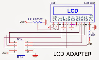
The circuit is in three parts. One is DDS Controller board consisting of the AD9850 and PIC.Second board consist of LCD display 16*2 , I have used chines JHD 162A. Third part is the Rotary Encoder and Swithes and the Flexible ribbon connector between the two modules.

A little story of mine.:- I had bought two DDS AD9850 modules from ebay (Om Priyashlok Arya). Then i was searching for the controller. Tried few known sources. But, there was some sort of problems like the genunie PIC was not available ,There was problem in programming. Another ham did not respond to my request. I had tried all the known sources. Some said you have to wait
 The DDS VFO
This is the original design by the VU2UPX himself. On my recent visit to the mumbai by chance i met the vu2upx and he promised to help, gave me PCB and programmed IC.  It turned out that his design approch was very different and genuine so that i could not search/find the ckt on google. Finally i gave up and sought his help in making this DDS VFO. I am in process of finally running and will update the information ASAP.

My request:- vu2upx is a very busy person. Friendsplease, if you have any query , questions please put it on facebook group and usually he responds within one or two days. thanks.

Tuesday, October 8, 2013

TA7358AP

I have fallen in love with this IC. It is cheap, easily available and usable to make a Mixer, DSB modulator, Demodulator and on first try it works. I have bought it from Raj Kamal Electronics , Lamington Market, Mumbai for Rs35/- a piece on bulk purchase.

From the datasheet i had predicted that it might be useful to me but never tried one. First i bought it about  morethen 15 years ago. I could not test it. B ut in 2011 i got a chance to work on it.

From it now i make a Direct Conversion receiver. 7058kc DSB modulator using the cheap 11059kc and 4000kc xtals. It uses two 7358 ic and two oscillators. I have made one Premixed oscillator using single 7358 and two oscillators.

Once my scanner starts working will share the circuits. Also dont forget to visit the py2ohh.w2c.com.br web site it has wonderful resources and ideas.