Saturday, September 26, 2015

RF Indicator

Indication of the RF has a very important role in transmitters. I saw this ckt on farhan's blog. It is a very clever and clear use of the simple diode detector. I was using the peak detector for Rf indications etc but this is a good one. Its simple, it works ,
 
please not :- it does not accurately measure or measure anything at all, it just indicates the RF level. When there is voice peaks, it flickers in sympathy with the voice.
 
For CW the presence of RF is easy task but for voice modulation its difficult. For my xtal controlled CW/DSB tx I use small homemade receivers but nearby receivers is being overloaded by the transmitters and we should not use our sensistive receiver during transmission. Its front end will be damanged....
 
Put it on the final linear amp.at the output. Ckt is self explained. Change the R according to the power level of the amp. Please don't use the preset or variable resistor, that might break disturb the Rf network.. he he..
 
For R try quarter watt carbon resistor, 10k to 4k7.... enjoy the flicker. Functionally similar was used in VWN- Tx but that was in DC current path.
 
In my experiments, I had used two linear amplifiers. One 2watt for driving my big 20watt linear. I did put this indicator on small 2watt linear.  At one point in RF when i increased RF level, there was constant light on LED, that means the High local stray filed from big amp was coupling and driving the LED. So I should have put the RF amp in small boxes and also put the this indicator on big amp....so keep this in mind when you are using two amplifier and two indicators shows the different dances... he he anyway it works.....
 
Wheel is here Enjoy.

Saturday, August 22, 2015

Pre-Mixed Oscillators

It was not possible to make the stable VFO due to many reasons, mainly lack of styroflex capacitor, not available suitable slug inductor, variable capacitor etc.

Then I wanted something which put me at a spot so that my QRP experiments can be built reliably.

I experimented with various designs , two VWN 40 meter transmitter, two my own CW /DSB transmitters etc.

The Xtals available which can be used directly on hambands are few.

i.e
1843 kc
3579 kc
7159 kc
14.318 Mhz
28.322 Mhz ( beware some are not fundamentals)
,
also 14166kc, 7050kc ,14060kc but very hard to find. They are special order xtals so costly.

But, I can find the 11059kc, 10mhz, 4000kc,4194kc,4433kc etc And using the mixer techniques we can arrive at some frequency which can be used easily.

This is the working module on 14194kc +/-10kc. {Of course it worked for a day on test bench he he... }
scrapped TA7358 mixer board
There is one xtal oscillator 4194kc, A gilber cell mixer in ic TA7358AP LO here is 10.0  Mhz. The output is amplified selectively and filtered.

One thing I learned from vu2dev is putting the pins for interconnections. This is new for me. As previously major fault with my projects were the interconnections become loose during the assembly or boxing. So that's good.

Schematics,,,, wait a little.... please 22aug2015
Stuck once again at the coils... it needs some tweaking. There is some problem .....

31August 2015:

To solve it I first scrapped the coil, amp stage then the ta7358ap stage itself. This DBM got rotten due to over drive from the oscillator. WTF.

Why this happened ???? due to my minor mistake of not using the 1k preset which I previously used in 40 meter mixer. This 1k pot was helping in reducing the power going into the chip. My buffer puts really big voltage. Scrapped above board. Making new board.. once again..... 

04september 2015:
Ohh my god this was the reason my DSB exciter 14194kc did not work.... I need to correct that one.... and use it... good idea...... Removed few parts. Making  it work.

Sunday, August 16, 2015

20 Meter band Superhet Receiver (II)

I tried first experiment with eaty-beaty receiver but something got problematic and could not cure it in time so lost interest and attempted this receiver. have a look.

1. Front End
2. RF- Mixer
3. IF Amplifier
4. Product Detector
5. AF Amplifiers

AF Amplifier
My LM386 did not work ? I replaced atleast three new LM386. Was wondering what is happening. Ohh it might be Chinese dump. So took few transistors. made  complimentary pair small Audio amplifier. It works nice.
 

this is my first AF Audio amplifier made from all discrete components. It was just 20 minutes affair and worked at first time. But, power is low. Need to reduce the 470 ohm  resistor. But, that reduced the audio. So, it is good as it is. I used whatever components I had. Nothing special. only transistor AF amplifier. I feel it need some more audio gain in pre-amp. I increased the gain in front end RF amplifier. By shorting the 10 ohm degenerative capacitor. Oh boy it increased sensitivity.
 
BPF

The coils are made on standard 8mm drill bit. So, it can be reproduced anywhere all over the world. When I used 21 turns with 100pf it resonated around  10 mhz. Then empirically, reduced few turns one or two at a time and changed the pf to 68pf at one point it resonated. Finally at around 15 turns it gave resonance in 20 meter band. 14.200 mhz. That's okey. Same way done the second tank. Then linked them with 10 pf. That will give me enough bandwidth.


IF amplifier & Xtal Filter

IF amp Xtal filter
The If amplifier is simple two stage amplifier. I did not use the LC tanks. Due to non-availability of toroids/tuned cores etc. So, simple  resistor coupled amplifier are used. First Amp is classical class A with negative feed back. Used BC547b. Second IF Amp is a cascade one. Using two transistors BC547b+BC547b.

The xtal filter. I was little skeptical at first. The xtals were matched. See previous posts for xtal filter making. Its purely experimental. I have no instruments to measure the bandwidth etc.

xtal filter

I am not puritan. Whatever works is mine. So, this somewhat wide but okey for me. Only caution I took is short leads and clear soldering. Don't forget to ground the metal case. No extra shielding is needed. The filter is the "secret" of RC coupled amplifier.

VFO:-

4 Mhz VFO
Generally I use the  Collpit oscillator, Emmiter follower design. for base bias 100k resistor and at emitter 1k was used.  But, this time I used some different biasing method. A fixed base biased was used. 22k+33k. good result.

I used old trusted buffer with 470 ohm preset to control the RF going to mixer. This way I can somewhat control the mixer characteristics. Its stable. But, I have not measured its stability. Will put some slow tuning and box it up. Will use regulated 5 volt . LM7805.

Detector Stage:-

Sub Harmonics Detector
 

RA3AAE, sub-harmonics detector. See previous posts about it.

There is one common emmiter BC547b AF pre-amplifiers stage which feed audio to either the LM386 or discrete stage

Here is the ckt diagram of IF stage and detector.
IF stage & detector.
 
Front End BPF + Mixer
 
I will make pcb pattern and ckt diagram in deep-trace pcb designing program._
 
  
Receiver ( BPF, Mixer, IF amp, xtal filter, VFO, detector)
 
For further reading about these module just read my previous post. or email me. I will respond.
 
Further,
I will try to make one transistor audio filter. will make compatible 20watt cw transmitters using 4194 kc, 4286kc & VFO so I can be atleast heard by other hams. Once this is done, my "on air dream" is  over. Will try to modify it to DSB or SSB and will be end of days for  20 meter. And if by chance I get hold of DDS VFO, it will be good.
 
See you on air....
 
Boxed it. Performs reasonably good. I can say the stability is very good. Far better than my latest 40 meter transceiver. he he.....
73 friends.
de vu3inj.

Thursday, August 13, 2015

Heat-Sinks

I first learnt about the heatsink in my early days with VU2LEX around 1994. He showed me the calculations for his cwtx. etc But somehow I never need the heatsinks seriously till I made the IRF640 LINEAR in 2014.

My success with linear is mostly attributed to the first big heatsink I found from flea wendor. It costed me about Rs40/- about half dollar a two years ago. It was a Pentium computer heatsink. Then I found few in Mumbai lamington roads flea vendors and then from my local markets. As such these are not normally sold in shops. But, there is a shop in Mumbai which specially sells the very big  heat sinks, but it will be costly for a single purchase. (will appraise its name later on)

Here are the pictures of various types of the heatsinks available with me ( I am not selling anything he he ... these are for all my upcoming linear projects/devices)
(will update the pictures on 14aug2015)
Empirical calculations for calculating the heatsink temperature.

Basic formula for temperature rise VS area VS power dissipation.

Say your area is 1 square inch and dissipation is 1 watt, ther temperature rise in C is 130 degrees C

increase area to 10 square inches and the temperature rise drops to 13 degrees

130 * (Watts / Square Inches)

How to calculate the required area of heatsink.

the formula you want to use is 130 degrees C / Watt / Square inch

So say you have 80 square inches and the amp will be about 50% efficient so 40 watts dissipation That will be 65 degrees C temperature rise making the heat sink 100 degrees C at 100% duty cycle. SSB is around 30% AM linear would be higher.

2 to 3 square inches of surface area for every watt of dissipation.

Fins vertical is the most efficient heat radiator

Fins up second best

Fins down useless without a fan.


Thursday, August 6, 2015

VU3PUA ANTENNA

My friend, OM Rakesh Mishra, VU3PUA from Bhopal (Madhya Pradesh) on 20 meter band radiates 500 milli watt signal all over the India with 55 report. I pleaded him for the "secret". He kindly gave me the ckt diagram. With his permission I am posting this. Hope it will be useful to all hams.

He is a great ham, From Bhopal he did help in Nepal Earth-Quack Emergency comm. in 2015.  His blog is http::/vu3pua.blogspot.in

His transceiver is entirely homebrew of his own design. His transmitter is just 500 milli watt. I have seen many hams using big rig set to 5 watt and establish the com and then drop down to milliwatt, but VU3PUA use just 500 milli watt for all work.

Recently in August 2015 he has made a 6 bans SSB QRP transceiver using the Chinese kit. So, you are sure to hear him in all bands.

The values of the Inductance and capacitor is a as under....

Here is the circuit....
VU3PUA ANTENNA for QRP

I am thankful to VU3PUA, Mishraji for sharing this wonderful design and hope to try it one day. There is one or two more silent features which after clarification will put here.

I will try to put here  exact arrangement of antenna , mechanical constructions and their pictures. I am searching for the pictures in my database....

How to tune it ? put the diode probe with VOM meter / VU meter. Tune it for maximum deflection. Please use the analogue VOM. Don't use digital multimeter.

That's it folks, the wheel have been re-invented and use it.

Here is the latest update:- 07 Agust 2015

VU3PUA, 20 Meter band antenna

VU3PUA 20 Meter band QRPp antenna
Two pictures.

Radials are random length fitting to the QTH but alteast quarter wave and straight.  fThe Vertical portion is 16 feet 7 inch.  Quarter wave legth for 20 meter.

In the antenna pictures you will see the VHF antenna is also used with same cable and the tank prevents VHF going back to HF set.


Was awaiting  confirmation of  one small finer details regarding the size of the coil. here is the picture.  May be it is about 3 inch long and space wound.


Friday, July 31, 2015

15Watt Linear

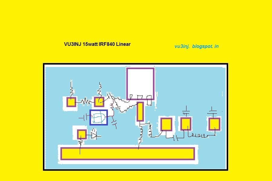
Here is the schematics and PCB pattern for my 15watt linear.

15watt linear component placement

15watt linear pad placement


Descriptions, History :-

I had made this linear by accident. My 5watt cw tx/ DSB tx was not giving me signal reports. I was worried ! What is the  problem ? Then it occurred  to make a single device linear . One ckt was interesting . Put queries in the Indian Homebrewers forum at Facebook. And lots of reply came. VU2RON, VU2ESE, VU2DEV and lots more friend jumped in.

Finally tried it with IRF510 but it went burst with 25volt dc power supply. Then changed the IRF840/IRF640. Both worked fine. vu2ese had suggested me to put some 200pf at the drain. VU2DEV suggested making a Pi-LC matching. He even pointed out the calculations in the ARRL handbook , which he had gifted me. But, I settled for transformer & toroids. Ron hinted on impedance transformation of this broad band transformer.

Then made it. I used Small pig nose baluns bought from tpsonline Bhopal. Put 6 togather. 3x2, Glued with water pipe glue and it worked. It did not heat-up. The biggest problem with the ferrite is that it heats up and freq response depending on the size and material. So, we have to take care of this problem.

I used in the input a resistive 3db pad. This db-pad solved my problem for loading the exciter, proper match etc. It was happy happy solutions. With pad some fraction of input power is wasted in heat. Its okey.

I put LED to indicate power supply presence. I put a protective diode 1N4007. Not shown here. The VCC line is a big one.  Instead of deriving 12volt from the pcb I used the LM7805 voltage regulator. The simple preset is used on the pcb to bias the gate of IRF. At gate a small value resistor 5 ohm is used to stop parasitics. If you have ferrite bead please use that also. Now, a days we don't find ferrite bead esily.

Filter is classic bilateral 50 ohm three pole. Simplicity. Actually 7 pole filter should be used for more spectral purity.

The relays for changing over the antenna etc are not used here as it was meant to be a beacon / CW tx.

Components & Schematics:-


vu3inj linear


Setting up the linear:-

this requires some care & instruments.
Put Digital Multimeter into 10A range. Set the current to about 100mili amp. Now key the exciter. Make sure there is RF. This will increase the linear current to about 1.2 Amp. Use the dummy load or dipole antenna. VU2PTR digital VSWR meter will indicate the 15watt. So, this is the set-up. Nothing more. Mind you the preset tuning is little trickey. Slight increase in the bias and power jumps from 5 watt to 15watt. At one point of time you will feel that heatsink is too much hot but there is no power increase. buck down a little... don't set it for constant 1 amp. at max 300ma is also good. Do little experiments but just care for heat....

This linear has been never tested on SSB. If I ever do, will let you know.My approach was use whatever is on hand. Till date I have made two linears and both work wonderfully. One is with me and one is with VU2TOO.

Heat sink:-

It is one of the most important factor in this linear. You ought to use a biggest heatsink you can find. Old CPU heasink is okey. I also use the fan.

On Air test:-
On one two occasion I asked for listening service from VU3INK now (VU2JYX ), VU2DEV and two more hams. I am thankful to you Kishore for being with me. My signal was good. consistently 55 to 57. In this I had not tuned my antenna at all. SWR was around 2.5, So, the signal reports are not bad.

Will update few more fotos of linears and corrections within two days.


That's it folks the wheel has been re-invented.

Use it and don't forget to customize the bells and whistles ( relays, heatsink , box etc)


Tuesday, July 28, 2015

Signing Off - VU3INJ

Something is simmering within me. I am just closing my station, it seems due to one reasons or other reason I am not able to put myself on FONE. For me CW is okey. My journey had been a topsy turvey. Around 1994 is started ham radio, finding the forms, filling it up, giving the exams, finding books for exams, learning morce, waiting for exam dates, meeting hams, brewing , homebrewing, learning the soldering from the scratch, understanding the semiconductors, valve, EFY, waiti...ng for the result, police enquiry, missing of files at wpc, my MP,member of parliament putting my case and then the licenses. How much this all took time... lots and lots of years. Now a days the person who gives exam withing 3 months start enquiring when their license will come ? I waited , prayed, tried to figure out, many friend VU2MAU,VU2MKV, VU2Mukesh desai, VU2EXP, VU2JF(Jivanbhai-sk),VU2LB, VU2FQ and many many more,VU2DK,VU2HEG (Yep Old man hegde) and many more (whose name i am not writing here )really helped me in one way or others. Still I am stuck at the build the bitx paradigm, making of radio has become guardian knot. I don't know what to say. THANK YOU ALL. I am disheartened at the murphy looking me in each corner, each time I do something it breaks one vital element. May be this being on air is not for me. 15 years, this much efforts and still not on air.... I can say no more. Let it go indrajit... let it go

I had tried BUILDING, i tried BORROWING, i tried BUYING. But, found nothing that can put me on air. 25W decent can put anyone on air. So, the homebrew dream was wrong ? Some peoples are getting air with just 500mw (vu3pua) or 5watt. Why i am getting everything that has one or two minor fault. It never works for the fist time...I wished VU2OO had gifted me the Major havildar sing ( ?) RM96 for 20 meter. I wished had VU2ATN gifted me a working rig instead of coaxing me to build the bitx. Buying 50k rig is beyoung my budged. May be no -body understood the gravity of my situations and problem with murphy. But, thank you all.

Wish is a big if and not if. Wish is not a true reality... i could have wished god given me so much money that i might have been able to import the rig, I should have wished i never choosed the ham radio. I could have wished Niar Hyderabad had given me club rig. I wished i should not have wasted 15 years on a dream. I wish i should not have written signing off note.... wish is a never ending thing.....


WISH IS NOT A TRUE REALITY. Many peoples are really not understanding my words, meaning and more.... this is the real signing off note.


My jinx is simple........... I am not able to be on air. And once on air with brewed, borrowed, bought or begged rig, home brew or commercial, then murphy will let me go. Jinx will be broken and then even 500milliwatt signal will give me good mileage.... thats it folks.....
Listening for final finale...

You peoples had been a good company. will miss you.

73
***