Showing posts with label vu3inj. Show all posts

Saturday, December 5, 2015

Madras Disaster, december 2015

I was seeing the human tragedy at Madras(Chennai, India),due to the natures fury. Even if nature's one element increases Air, Fire, Water,Earth all becomes cause for the disaster. If we are lucky the disaster is small, but there is still loss to the humane and infrastrutcture and in long-run to economy. First thing, we wish in this situation is water, food, hygine, warmth blanket and message from our family they are ok, we are trapped here, save us. In this last thing related to the communications, as a ham we can help them a little.

I look around, am i disaster ready ? Yep, my antenna is up. i have light(electricity), what If ? my light goes out,,, for 5 hours i can use a 40 meter analogue receiver on car battery. After that nothing. sorry, i do not have transceiver...

What ? i can not afford commercial set up, not able to build one, and great ham not able to provide the pre-build air worthy transceiver. But, there are many designs, bitx, vu3gcm,rm96,nr60,vu2atn,various dc receiver,r7, gr7, jota,HF1 etc etc.... there is a gap of simple tech. We have very hi-quality tech,sofisticated, digital, software but not a simplest one.

In the early years of 60-70 our maritime mobile were able to accurately transmit the distres signal in morce ? they were right on frequency ? how did they do it.

Answere is simple 2182kc, 6725kc , 455 to 465, 500kc etc were maritime frequency. I have seen the emergency set powered by a crank shaft, CW, DSB with portable vertical antenna and they all were xtal controlled transmitter. I have seen fixed frequency receiver also to receive 2182kc the local oscillator was 2682kc xtal, IF was 500kc. So, you got two frequency receiver. Damn ! the tech is there.

Our, need of the day is small powered cw or fone transmitter with portable antenna so that atleast they are able to radiate some effective signals around say 50km from the locations and if power is there and antenna is high then full range with big linear. We should go with new tech, that is progress but at the end of the days the morce code will come handy. When power is out, there will be less QRM.

There are many xtal cheaply available i.e 14.166mhz, 14.318mhz, 7.159mhz, 3.597mhz, 1843kc, and 10.000+(4.000 / 4194 / 4433/4286) for twenty meter, 11059-4.000 for forty meter. All our problem of hams not on air can be solved. VU2FI sir, if we import some xtals in bulk from dx or specially made say 14194kc. Let us make some simple design of one to two watt transmitter, simple transistors as active device, less dependance on special ferrite, and simple receiver (DC or Superhet )with sensitive enough to work another local qrp. If person is on air, we can depend on it. our air wave will be busy and no one has the chace to grab it up. Guys, think over it. otherwize as you have seen the everage age of hams at hfi2015 was more than 45 plus. Farhan we expect & request you to help as you can think out of the box, it is out of your league or not intune with what you are doing but we seek you to help. VU2RBI, VU2FI this is answere to your quest what will help ham not to dry up.


***
I put this ideas to the indian and foreign hams. From the response/comments I can say, may be we are not realizing the potential of this old technology. May be electricity and civilization stays with us forever ... BEWARE  there will be few black days also.........
***
My one friend put this on net. I liked the content, as it is useful.

Most Chennaites and people in rest of TN have only WhatsApp connectivity, so please copy this
story and spread through Whatsapp.

As the rescue operations are underway in Chennai, the focus should now shift to how best people can ensure public health and combat the outbreak of water-borne diseases as it is often difficult to maintain hygiene during clean-up operations.
The News Minute has compiled a list of dos and don'ts based on our conversations with doctors. Most of these... are home remedies that you can execute even without power and medical supply. Spread the word and stay safe.

> Using sari as a filter can reduce the chance of cholera and the water-borne diseases. This has proved to be an effective method of filtration in flood-ravaged countries like Bangladesh, with researchers from the US establishing. While boiling water and then filtering it would be more effective but in cases where people have no access to gas or heating mechanisms, filtering water using the folds of a sari is better than no filtration at all.

> If you have no access to drinking water, collect rain water in containers placed on your terrace. This can then be boiled and filtered for use.

> Do not stand in stagnant water. With sewage water getting mixed with all water sources, standing in these stagnant pools can lead to leptospirosis.

> If your food stock is running low at home, take a litre of boiled water and add 5-6 spoons of sugar and 1 spoon of salt. Drinking this at regular intervals will help in keeping the hydration levels high.

> In areas where the water is knee-deep, add bleaching powder or salt to it. It works as an effective disinfectant and also prevent bacterial diseases from getting transmitted.

> For those with access to medicines, stock up on ORS packets to prevent diarrhoea and antiemetic drugs to prevent vomiting.

> Have freshly cooked food that's been heated to boiling point. For those with power, avoid refrigerated food to the maximum extent possible
***
It seems our senior ham VU2FI had set-up a emergency communication room at Banglore and handled 3000 messages and helped in disaster relief in 4 days. Hats off to those hams. Freq was 7070kc, and ecolink , VHF etc were used. Hope to hear and learn from their experience for disaster preparations.
***
It seems the SIARS-Chennai , also have its own view. Will collate it after they speak it loud.
***
Personally I have no bias, I welcome all the voices pro-con and others. Life is multi-dimensional, if we have different views, viewpoints then better we understand the situation.

 IMHO we need hams who can interface with giant multi head  government on whom we depend for our joy. There are who really wants to work in field and shy away from all limelight. There are those who comes on air, there are those who just  tinkers.

It is a very expensive hobby. I have seen many persons who also developed other hobbies, numismatics, photo, tracking, mountaineering etc and survived the harshness of ham hobby.

So, ultimate aim should be enjoyment. Whichever way you find joy enjoy it.

Monday, October 19, 2015

Mobile Expedition

Here is write-up for my short expedtion on HF 14.315kc.
The following "image" inspired me to make my own experiments, which I was post-poning for sometimes.
vu2mau_7388_Small_Emergency Mobile
After hearing from the GJ1-CD-7388 mobile of VU2MAU. I was inspired. Why I also don't put the receiver on my bike.

As I did not want to be big eye-catcher and explain to the public and police what and why I have put antenna on my bike ??? he he. But, first time I took my original license with me to make them understood in case I find some idiots.....

So I took a 1 meter telescoping antenna, put it onto the small direct conversion receiver. See my blog for xtal controlled ra3aae poliakov 20 meter receiver. I used three 4.4 volt battery to arrive at 12 volt. So receiver was ready,concealed into a cloths carry bag I checked signal upto 6 km. It clearly gives me the beep beep on 14.315kc. Wow ! tx was pumping 20 watts, antenna was dipole, I did not care for SWR. It should be around 2.7 to 3.0 a very high but okey for me. It was a very nice experience. Almost at all places the signal report I gave was 55 to increasing into 59 at one heigh place and near my qth... So, good experience. I will make proper quarter wave antenna and another direct conversion receiver with good gain.... will see how far my ground wave goes. This auto-beep for testing is the penalty for being lonely and only hams....

If I make the 40 meter transmitter 7059kc and test them, its possible that I might reach my friend at 100km with 20 watts.. Waiting to hear from other friends what is their experience with vertical antennas for mobile use.....

10 December 2015
I find this article very useful... have a look for portable antenna.... http://www.zerobeat.net/g3ycc/yccwhip.htm 

Friday, July 31, 2015

15Watt Linear

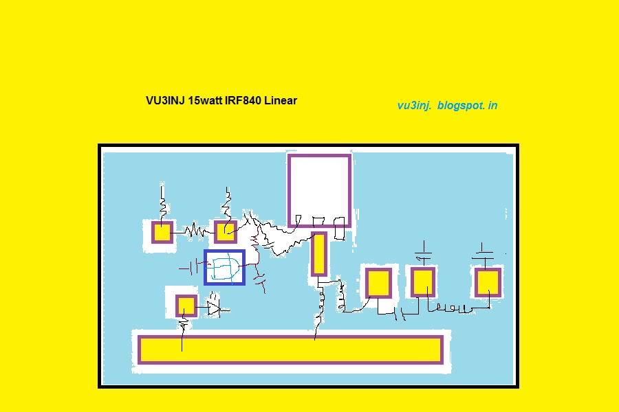
Here is the schematics and PCB pattern for my 15watt linear.

15watt linear component placement

15watt linear pad placement


Descriptions, History :-

I had made this linear by accident. My 5watt cw tx/ DSB tx was not giving me signal reports. I was worried ! What is the  problem ? Then it occurred  to make a single device linear . One ckt was interesting . Put queries in the Indian Homebrewers forum at Facebook. And lots of reply came. VU2RON, VU2ESE, VU2DEV and lots more friend jumped in.

Finally tried it with IRF510 but it went burst with 25volt dc power supply. Then changed the IRF840/IRF640. Both worked fine. vu2ese had suggested me to put some 200pf at the drain. VU2DEV suggested making a Pi-LC matching. He even pointed out the calculations in the ARRL handbook , which he had gifted me. But, I settled for transformer & toroids. Ron hinted on impedance transformation of this broad band transformer.

Then made it. I used Small pig nose baluns bought from tpsonline Bhopal. Put 6 togather. 3x2, Glued with water pipe glue and it worked. It did not heat-up. The biggest problem with the ferrite is that it heats up and freq response depending on the size and material. So, we have to take care of this problem.

I used in the input a resistive 3db pad. This db-pad solved my problem for loading the exciter, proper match etc. It was happy happy solutions. With pad some fraction of input power is wasted in heat. Its okey.

I put LED to indicate power supply presence. I put a protective diode 1N4007. Not shown here. The VCC line is a big one.  Instead of deriving 12volt from the pcb I used the LM7805 voltage regulator. The simple preset is used on the pcb to bias the gate of IRF. At gate a small value resistor 5 ohm is used to stop parasitics. If you have ferrite bead please use that also. Now, a days we don't find ferrite bead esily.

Filter is classic bilateral 50 ohm three pole. Simplicity. Actually 7 pole filter should be used for more spectral purity.

The relays for changing over the antenna etc are not used here as it was meant to be a beacon / CW tx.

Components & Schematics:-


vu3inj linear


Setting up the linear:-

this requires some care & instruments.
Put Digital Multimeter into 10A range. Set the current to about 100mili amp. Now key the exciter. Make sure there is RF. This will increase the linear current to about 1.2 Amp. Use the dummy load or dipole antenna. VU2PTR digital VSWR meter will indicate the 15watt. So, this is the set-up. Nothing more. Mind you the preset tuning is little trickey. Slight increase in the bias and power jumps from 5 watt to 15watt. At one point of time you will feel that heatsink is too much hot but there is no power increase. buck down a little... don't set it for constant 1 amp. at max 300ma is also good. Do little experiments but just care for heat....

This linear has been never tested on SSB. If I ever do, will let you know.My approach was use whatever is on hand. Till date I have made two linears and both work wonderfully. One is with me and one is with VU2TOO.

Heat sink:-

It is one of the most important factor in this linear. You ought to use a biggest heatsink you can find. Old CPU heasink is okey. I also use the fan.

On Air test:-
On one two occasion I asked for listening service from VU3INK now (VU2JYX ), VU2DEV and two more hams. I am thankful to you Kishore for being with me. My signal was good. consistently 55 to 57. In this I had not tuned my antenna at all. SWR was around 2.5, So, the signal reports are not bad.

Will update few more fotos of linears and corrections within two days.


That's it folks the wheel has been re-invented.

Use it and don't forget to customize the bells and whistles ( relays, heatsink , box etc)


Saturday, April 11, 2015

SKCC-VU3INJ

MEMBERSHIP INFORMATTION
SKCC: 13864
Join Date: 11 Apr 2015
First Name: Indrajitsinh
Last Name: Rathod
'On Air' Name: Indra

Registered Callsigns:
Current Callsign: VU3INJ
Current City: Junagadh
Current SPC: IND
***
I have three Russian army keys found from the junk at alang ship breaking yards around 1994. I had one brass straight key, this one I could not find now.

I am trying to do daily pracitice and operate the slow cw at 14314kc. There are few takers on SSB/CW at this end of the band. So, sked works for me. My transmitter is a xtal controlled one. I use 15watt of powers. I have separate antenna and Direct Conversion Receiver for it. Its a good one and works fine. So, drop me a message on the facebook or gamail or LL and we can work the sked.

Even if we are able to exchange the RST, Call Sign I will be happy to send the QSL-Card in INDIA. or continent INDIA ( AP2,S7, LANKA).....
***

Centurion Award:No Centurion Award Status, Tribune Award:No Tribune Award Status,Senator Award:No Senator Award Status, DXC Award:No DXC Award Status,DXQ Award:No DXQ Award Status,Maple Leaf (Yellow) Award:No Maple Leaf (Yellow) Award Status,Maple Leaf (Orange) Award:No Maple Leaf (Orange) Award StatusMaple Leaf (Red) Award:No Maple Leaf (Red) Award Status
Maple Leaf (Gold) Award:No Maple Leaf (Gold) Award Status
Miles per Watt Award:No MPW Award Status,,Prefix Award:No Prefix Award Status,QRPx1 Award:,No QRPx1 Award Status
QRPx2 Award:No QRPx2 Award Status,Rag Chew Award:
No Rag Chew Award Status,WAC Award:No WAC Award Status
WAS Award:No WAS Award Status,WAS-C Award:No WAS-C Award StatusQSL Buro Status:You have No Envelopes in the QSL Buro
***
To fill up above empty scores, friends have a sked with me.
c u agn on air. de vu3inj.

Tuesday, February 10, 2015

Renewal of Ticket

Today I got the license renewed for my lite time. That means till I die or it is recalled or I upgrade..... Really feel nice..... Now, time to print the QSL cards..... This was my first reaction on10 feb... I put the license in the locker. Today on 13th feb wanted to put this here in blog and I saw something different.......


I am just puzzled why upto 2017 I paid for life-times fee i.e 2000, paid penalty for late renewal.

Who is playing with me ? May be its clerical error. May be its practical joke on me.....  I never heard that license is renewed for only Two years... IMHO instead of adding 20 years s/he added just 2 years.

This is not the first time Min of Com. played jokes with me... When I applied for the license my result was mixed up with another person. he received my letter. I received his result. Instead of giving me my letter he sent it demanded that I give his letter. What a jerk he was.... After that police enquiry, verifications , I paid up fee it went missing. Then once again paid-up  fee .Then I had to wait aobut 5 years. On insistance of my local Member of parliaments personal visit to WPC. Yes sir she visited personally to WPC... Atlast they assured I will get my license in 11 weeks, but it became just 11 months.

When I applied for the renewal  recently. For a year they just sat on my applications, Then took one years to ask me about the fee. Then they took one year to give me license. Even that is given for 2 years... Who is messing with my life.....

NO need to be Happy. No need to print QSL card... No need to Thank God.

If you are listening, hear that :: God you sucks..... better get your nappy changed......

Wednesday, February 4, 2015

14194kc DSB transmitter

The most of beautiful band for me is the 20meter. I fell in love with it reason most of the time I can get plenty of the station for listening DX and local. Some are QRP/QRPp/QRO.

Its time, I make the DSB Modulator and be on the air. Lets see how much I fare.
Started the 2Watt linear.

This will be my third prototype. First stage is the 2N2218, Second transistor is IRF510 both working on the 12vdc. This time I will be making the power-supply little up 14 volts. ie LM7812 plus LED.

Plan is to drive the VXO of 14318kc, one DSB 14194kc, 3.68mhz ceramic VFO plus Quadrupler. And the DC receiver integrated with it.......

***
VU2ESE has designed this linear and it gives about 5watt when carefully made. But ,I call this 2watt as to me it gives me just 2watt without any special care. Happy, this is best for our use.  I could have tried broadband RM96 1watt amp, but that needs more toroids/components
my toroid/ferrite source ( I do recommend VU2PTR for toroids)  (For balun core I bought from tpsonline )

Here we can use the simple plastic pipe for IRF510. And just one balun for its driver. For RFC use the CFL lamps cores. What else you want ! This ckt is best made on the veroboard ( Yes sir !).

A small heat-sink is needed. 2inch by 2inch (5cm by 5 cm square or rectangle aluminum will suffice). But don't over do here. use small piece as heat dissipation will be low.

One thing I remarked that we need 24swg copper wire with just 2-3 twist perinch for biliar winding. When I gave more turns about 6-8 turns during the winding (sliding the wire from cores) I feel insulation was cracking. not joking. I realized the mistake but somehow if this does not work I need to rewind the toroid for IRF640 ( the after burner power amplifier)

05-feb-2015. Finished most of the components. Winding the second set of coil incase the first coil does not work as it has low number of turns. Prepared the heatsink from aluminum. It was in L-shape. Cleaned it. Flattened it with the wood batten and small hammer (250gm). Then with the help of Jig made it into the U-shape. Filed the aluminum surface clean and fat. As the transistor has to made the contact with it. So, it must be flat atleas the contact area. Then put the drill. The heatsink should be outside the pcb not near or on the 2n2218 transistor. Otherwise feed back may arise. I did not had the insulating kit but will use small plastic piece on top bolt to isolate it from Vcc.
Lets hope it works as I am trying an old tech in the days of the DDS Microprocessor controlled VFO........

But my hunch has proven right sofar.....this will also work

All the fun is in making and using it to drive a big amplifier. Yellow are the biasing network for IRF and 5volt dc supply. In blue,The crown heat sink is the driver transistor. In he tblack is the IRF amplifier stage. In corner  black LED to indicate the DC supply...........
One thing I noticed that in the previous two attempt the preset was atleast 2 hole apart from the two 100 resistors... here that is the mistake. So if you are making atleast put the preset 3-4 holes away from the 100 gate resistor. This way during the tuning the screwdriver just don't hamper the coil.


Please use the dedicated LM7805 here. As the work is in progress  at the input and output we need to put one 470 mfd, 25volts each. This way It gives a good stable 5volt. There is one LED placed so it burns the voltage during switched off and reminds me that there is voltage.

I have made a point to add atleast one LED per board so that quickly I can know atleast there is voltage and power supply is not at faults.....


Now the back side of the vero-board.


Here it is important that the IRF510 is soldered in the back side to reduce the lead length. IRF is not inserted into the holes. Just placed over it. If the lead length is big it will sure to oscillate, be it in the copperboard, etched pcb or any damn thing. Make sure the lead length is small. also notice the gimmick 10 ohm resistor on the gate of IRF510. I have also used the 100k+0.1mfd capacitor for negative feedback. This reduces the possibility of the parasitic oscillations. I did not have the insulation kit for transistors, so using the mica washer only. Of course the heat conducting paste is liberally applied. The gates impedance is 100 ohm so it needs more drive from 2n2218. That's okey.

I could not find the round ferrite core used in the CFL lamp. So used its transformer by breaking its half E core into a C and then placing a small slab on it so it becomes sqare bobbin. I also liberally applied the plastic adhesive used in the water pipe / plumbing.

work is in progress will be update from time to time.... whatever the outcome.....

07 Feb 2015.
Working on the Quadrupler and Amplifier. May be today or tomorrow it will be ready. At this time only one band will be operational. But will make it for two bands.


3.68 mh Ceramic VFO + Quadrupler is almost ready. Two Coil needs to be tested/ tuned for 20meter band.  One small amplifier will be added which  will drive a CW as well as DSB modulator plus DC receiver. Lets see......

Actually I wanted to make this for  20 & 40 but in a bit hurry to be on air.... anyway will make dual band also. On searching the net I found somedifferent filter which has the 50 ohm terminations impedance using the capacitor divider method. That's good. So, we don't have to put a tap, that results in physically strong coil. When we put the tap it slacks a little bit.... whatever works is okey for me. So when you re-produce make sure it  works for you.... I don't intend to make another or repeatable thing. Each prototype will be little different, learning from failure and success of the previous modules and new information.

The modules first tank i.e quadrupler required extra 47pf. That means it required (47+68+150)=268pf total with 13 turns 20swg copper wire wound on the 1/4" drill bit. I chose the dril-bit as it is a very precise tool then lots of other available items like sketch pen, plastic tubes etc.

On second thought I think a small 2db pad will solve a harmonics problem. 470 ohm 10 ohm 470ohm preset to control the RF. This was quadrupler get minimum power required without producing excessive harmonics. I will not put the signal directly to tx stage. Instead make one class-A tune amplifier with emitter degenerations. So that harmonics are down further. Will also use more filtering at the  small linear stage.

QUADRUPLER MODULE
One friend recently asked why taking this much pain. I said I have in the last year spent atleast 20k in buying old marine receiver ( lasted 6 month), LRR40 receiver ( that piece never worked from day one), VHF DR150 that guy cheated me. So I don't trust. I will not buy anything from the hams. Only VU2PTR & VU2KD was able to give me something which worked as they claimed.

So I am making this much effort to be on air. First will be the CW/DSB tcvr 15watt. Then will move towards the other band.

The receiver was tested with this quadrupler module. It gave me good quality signal in speaker even with 15cm wire as antenna. It has too much gain so there is need of proper shielding and filtering plus 3db resistive pads....

08feb2015

At night time again tested the linear module. There was short developed due to the that green capaciotor. Removed it. There was no connection/ dry connection on Vcc rail....
need some work..... there is some carrier leakage...

This is the first time TA7358Ap module is leakage of RF. On verobaord it was very nice. It might be due to the  copper planes instead of small pin socket...(. it needs some pads / resistor to curb the leaks...)

09feb2015

finally plugged the problems. At the 150 mw pre-driving amplifier on the  DSB modulator put one 10k resistor across the 4:1 transformer. Then things settled down. It still producing more power so will have to put some pad at the IRF510 output. Signal is very clear and clean. Will put one filter after IRF510 amp... Starting to brew the after burner (using IRF840) and the cabinet, VFO. So I will have three things on this TX/ CW full band, DSB on 14318kc xtal and DSB on 14194 kc ......

Half success...One day one day, I will be transmitting ham....

work in progress........

(this ends here, next will be actual on air test and other things.....)

THE WHEEL HAS BEEN RE-INVENTED use it as given.

( Till August 2015 not tested it on air. oh the damn 24 Vdc power supply.Will drive a big linear with it. )


Monday, January 19, 2015

CW TX 14316kc

RF Linear
Last year made a CW transmitter. Power was very low. So decided to make a linear, then  after a year my cw tx is perfectly working with this  homebrew linear.

Here is the picture.

All details will updated later on. Atleast this is working......( updated as on 27jan)

Main power supply is the 24-0-24 @5amp with 0-12 @1amp . The cheap computer fan is used to cool it. The bottom plat is a thick metal one. Used as a heat sink.

One 12v dc @1amp, white box is used to supply the power to swr meter and keyer. Here the SWR meter requires the reverse polarity power supply.


The open box is exciter with having its own power supply on right had extreme. Well I can drive the exciter from the main transformers... will do that.... one friend said this much power sources.... well its on the assembly bench so I took liberty of using more....

Here is the ckt diagram.


linear amp after modification


(with input 50ohm resistor exciter can not drive amp
so removed the resisotors )


The RF Power Amp is used to drive the inv-v dipole antenna. Antenna is on the roof top....

Inverted-V antenna

On first test, i tried to load the dipole only 12feet from ground. But could not get the report. Well on suggestions, I made another antenna on the top of building. It was not cut to exact freq. Bought 20swg copper wire. 100 gram at rs.60/-. ... Used common dish wire to connect with TX. The plastic tube used as end insulator. Antenna was done in clear hurry..... but it worked well....

Used 20watt RF power. The SWR meter shows me the 3.0 reading. Then 2DEV gave me hint to put the antenna away from rooftop about 10feet with some plastic pole. I used a bamboo. then SWR reduced to 2.6 ok. One important thing I learned that for the receiving you can put dipole anywhere but for transmitting you must put your dipole/inv-v ver high and without any obstructions ( metal building) tree might be not that much trouble....  Put antenna atleast 30feet and up and you can punch a hole with 20watt north to south. For 5watt I got about 55 report. for 20watt about 57 report.


On my request 2KD also suggested few things. Well as the rooftop renovation work is going on will assemble/modify the antenna next week and try to have cw/dsb toway contact.

My test signals could be heard all Gujarat, sought india. But, the central india and Northern india I could not get the report....

What I feel:::   In the secondary school you get your first kiss..... (its different matter I have never got a kiss).

But atlast I have become the transmitting ham. Will modify it to DSB and hook up a receiver.

There are many hams to thanks. They helped me in varous stages of deveoplement by moral supprts, pcb, guidance, critical reports, critical words and above all kept my company....... 2TOO,2KD,2DEV,2UPX, 2PTR,3YFD,OM Ashok khachar, OM Vagishetty, Om Gurudata, 3HMM,3HML,3JOJ,3JOG, Om Mehta- Jamnagar, ( Last year during cwtx exciter time 2RAK, 2ATN,2UUU & 2ESE,3SXT,3SXN,2ORO....) also land lots more..... THANKS.....

Saturday, April 5, 2014

guarat earth quake

in the year 2k1 there was richter scale 5 to 6 magniture earth quack all over the saurashtra peninsula and kutch regions of the gujarat state. Its epicentre was near the bhuj city in kutch but after shock and effect was felt all over the regions. Even my home was also damaged in Junagadh. During this time i had only valve receiver and marine modified vhf which did not worked properly.

I did not go to the are but i did what i could. I monitored the signals and maintained the records.One of my friend when we had the eye-ball qso at my home and saw my logbook copied few entry. He remarked, we did only roughly maintained the log book at g'nagar control room, as it was very vital to keep communications going on. your book is correct based on this we will verify our own !. Thanks for compliments.

few pages


Thursday, June 6, 2013

40 meter cq

At last i have made the vu2vwn qrp tx running about 3 watt. It is very stable due to the crystals. Freq 7060 Khz. Keying is also good. Only problem is that it is for cw (A1A). Either it needs to be run into AM (A2A) or DSB (J3A) for voice communications. 

After putting it in a box will try a small linear using  mosfets or may be design a new DSB tx from the scratch.
my cw call will be

cq cq cq de vu3inj vu3inj vu3inj  AR.

vu3inj  de vu 2/3 ???  vu2/3 ? ? ? k
vu2/3 ???  ur rst rst 559 559 de vu3inj  qsl k
vu3inj ur rst ----- ------ tnx.

cq cq cq de vu3inj vu3inj vu3inj AR

If i use morce-code this is the conversations i can understand at most. I have not practised code for 7 years. Straight key. Seperate tx and receiver .NO full break. There is no NO QSK. Inverted-V dipole.  Timings about 7.30 to 8.30 mornings. QRS slow speed code. Please bear with me. If you hear me please reply in SSB or DSB.

Also requesting for a sked.
73
vu3inj
indrajitsinh 

LL9033, 6955- 03 , Anyone giving me SWL report will sure to get a qsl card.

20 Meter CW
As of 27Jan2015 will start working on the 20 meter with 15/20watt CW power. xtal freq 14315kc plus minus 1kc. I have no RIT so don't zerobeat me. My receiver is a very wide one. No filter just tuned ckts. Will be happy to work with you here also.