Thursday, April 25, 2013

4o meter transmitter


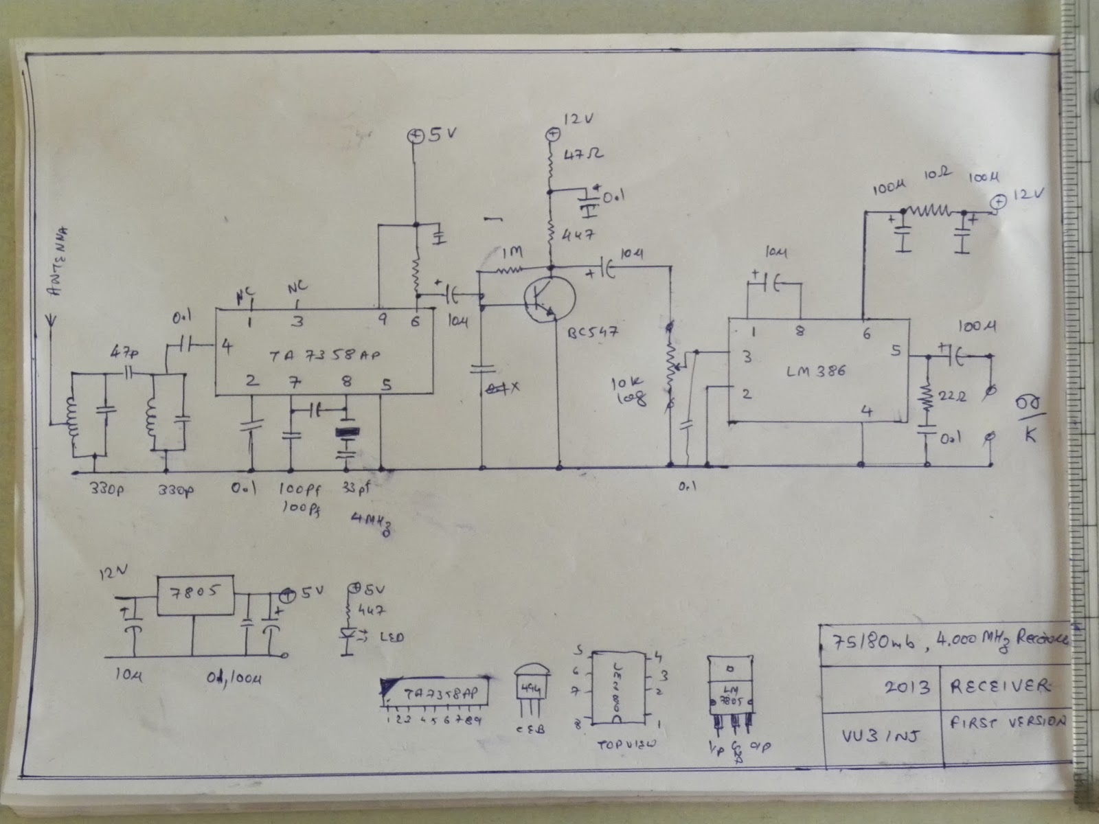
My VHF has gone QRT and 20 meter set-up is not good for local contacts. This is a right time that i should opt for 40 meter with its inherent regional contacts. There are few newly licenced( Jan 2013)  gr-ii hams  in my neighbrouring cities so they will be happy to work in AM as first transceiver. There is a very simple and effective time proven VU2VWN transmitter.  But, i want to give it a twist by going for xtal cotrol. 7 Mhz xtals are not readily available but a 11.0592 and 4.000 Mhz xtal are ten a piece. so, will make a Premixed oscilator using TA7358 AP and rest is vwn transmitter. When it will be completed you can work me on Ancient Modulation, Charlie Willy, MCW on 7.059 Mhz ( +/- 5khz). I also will make a suitable AM receiver. Using my 4 Mhz designs. If my circuit works it will be a new begining of local AM in saurashta region like it was in south india a decade ago.

( 27jan2015 out of this ham most have vhf and enjoying the local city regchew. okey with me. But no one has the setup to talk to me 100km on VHF)

As of Jan2014 , Planning to revive the first build transmitter and gift it to another friend in the Rajkot for a demo and to come up on the air with AM. There was problem of the tuned ckt in the final bd139 amplifier. Now, i have the LC meter so can re-check it. It is xtal controlled on a signle frequency but will make 28.322mc and 14.318 mc and digitally devide it to get more frequency.(as suggested to me by VU3SXT-Sandeep Lohia)

I will be not able to work with it as my LRR40 never worked and sait 40 meter band is also not working.(finally SAIT gone qrth around the end of the nov2014, I regret I bought the marine receiver, instead of the Chinese imported radio)

vu3inj, first vwn40 tx

 This was my first experiments with the vwn tx. it produced lots of qrm around house as the antenna was not tuned and loading tank not proper so discarded it but will sure to make it work after tweaking the coil.  It should work.

on 27jan2015:-
This transmitter works but lacks power. Clean power is aobut 3watt after that it produce more QRM then RF. This fact was found out with the power meter and receiver. So calls for a linear. This will be made soon.

Will remove this old box and make a more air tight, fan cooled box to house  a new VFO using ceramic resonator, one xtal mixer using the gate , one 7159kc VXO. This gizmo will put the transmitter in multifrequency mode. Will aslso add RF indicators, TX-RX control relays etc.... and then gift it.......

Saturday, April 13, 2013

AF Signal Tracer

Af signal tracer

This is an AF signal tracer built from very stable and easy to procure audio amplifier ic LM 386. Transformer (12-0-12 Vac, 200 ma ), two diodes (1n4007)  and voltage regulator ic LM 7812 provides a good regulatated 12 VDC. This 12 v dc is also taken out for power the ckt to be tested.

In the front panel a socket for signal input, audio volume control pot, LED indicator and ON/OFF switch is given.

Small speaker ( i recovered it from discarded pocket radio) is also put into the metal box. I have made a small  metal box from 24 gauge thin metal sheet. Due to the compact housing it's look is very good. It  also traces the AF signal wonderfully.

Earlier around (Y2K) i had the signal tracer made from discrete transitors but as i had shifted out of town it was ruined and finally i came home and need arised so this one is built for testking my projects.

At present only foto graphs of circuit is uploaded but will upload scanned circuit later on.


Sunday, April 7, 2013

BFO for measurig inductance


I use this ckt very extensively for knowing the resonance of my tuned IF stages (4mhz, 10 mhz), band pass filters , oscillator tank ckts.

As such it does not meaure inductance directly. For measuring you have to do the calculations. Connect Inductor-L and put 100 pf capacitor across it to make a tuned ckt. Now, read the freq in the counter. with the help of formula calculate the inductance.
Please note you will be not able to work out the RFC values by this as it likes only High-Q inductance !

I use this to circuit to tune the tank (L and C) for a given freq. when either L or C is variable or both variable , change them to get the desired freq in the counter. remove your tank (L and C) from the osc and put it in your IF stage or oscillator stage, bandpass filter and you are on the spot.


This little ckt has proved itself over the time. Use of styroflex and polyster capacitor in this oscillator is a good thing.  I use 12 volt regulated dc.

Years ago i used when i did not have frequency counter, with help of analogue communications receiver ( no digital freq readout) and other xtal marker used to put the tanks of 4 mhz IF into resonance...


Saturday, April 6, 2013

75 meter , 4 Mhz receiver


Original hand drawn ckt, Later on it is redrawn. See, the end of this post.


This was developed with intention of testing 4 Mhz IF of  Superhet Receiver design. I  check the 4 mhz DSB modulators signal and CW tone of 4 Mhz oscillators . Using  Xtal of 3.579 Mhz or any 80 meter band xtal  and  changig input tuned ckt of band pass filter (capacitor values) it can be used in the 80 Meter ham band.

In the earlier ckt diagram there was some mistake in showing 9th pin of audio ic (actually it is 8pin DIL package !). Now, it has been corrected and uploaded. pin 6 of ta7358 has load resitor of 1k.

Nb i was not able to use it as IF in my superhet receiver project design. I need to change input bandpass filter for IF.  As for 4 mhz cw, direct conversion receiver this is good.

receivers, s-129 hallicrafter, LRR-40, Superhet homebrew 20 meters

For the year i have used a homebrew ( around year 2000) receiver and few more direct conversion receivers on 20 meters. I also made transmitters.

My LRR40 experience was not good. I was told out of all the receivers only my lrr does not works but hope to get it rectify...

Friday, April 5, 2013

BITX-20


Radiating from the peak.


air core plastic former toroid 3


air core plastic former toroid 2


air core plastic former toroid 1


Making the air core plastic toroids.

Making the air core plastic toroids.

when i started the homebrewing, in the local market we had penty of the ferrite cores available as used in the 2 band radio receivers. I used extensively in my projects. Once i got the empirical vales of it everythig was piece of cake. But times chages. From the market all ferrite cores vanished suddenly.

In my TX-RX i used the 4 mhz as IF and Oscillators. There was no little pot variable capacitor in local market. My gosh what is happenig to the electronics things ! I have worked Valves, Transitors, IC, chips but i like making things with few components in old ways.

For my 80 meter receivers, i needed band pass filters, tuned tanks and everythig else was Xtal controlled. I thought why not make it instead of frustrating or buying expensive thing from DX. You will require frequency couter and Multimeter and also few tools.

Okay lets begin.

Choosing the PVC pipe:-

I choosed the PVC water pipe. It was coffee white. Water plumbig pvc pipes are thick and electrical pipes are thin. Pipes outer dameter was __ inch. I wanted a standard material which can be available in the local market and with time don't vanish like water tap washers or ferrites !

Making Plastic rings:-


In the press i put the pipe and cut with the hack-saw. Smaller the hack-saw finer the cuttigs. You will require less polishing. Now, mark the tubes lengh say abot 4 mm. after marking cut the tube gently,slowly also rotate it. If you work slow and carefully here better it will be output. Also check that hack saw is cutting in a line. Now, your plastic toroid is almost readdy. Polish it with emery-paper. don't use emery stone or metal-file, our plastic will damage them. See that there is no rough edges feel it with your hands. Using blunt metal road polish the edges. Atleast make more than 5 rings of exact size. Now, Choose your rings of equal sizes. Don't be disappointed, this little mechanical work is the tricky part and once it is over you will like it and will be expert.

Copper Wire:-
I used 30 swg wire of10 meter lengh for 4 rings, 1 meter was left. i.e each one requires about 3 meter of wire.

Making shuttle:-
For a sigle turn imagine you need to pass 3 meter wire each time across the toroids. how horrible ! First time i made this way and got tired. but, there is a cool wayout. Take a soft wodden spoon used in ice-candy. smooth it with emery-paper and make the both ends square. Now carefully cut the figure of V in both ends. You can also use 10 cm long 1 cm wide thin paperboard/cardboard. Spool all the wire say 10 meter on this shuttle.

winding the toroid :-
What is the problem ! Count the number and don;t forget it, don't twist the wire, see that wire is not knotted during the shuttle pass, leave 2 cm wire tail at start or put 3 extra turns and unwind it later.

Take toroid in left hand,take shuttle in the right hand and pass the shuttle, count the turn, slightly pull the wire (not the shuttle) once again move it. Slowly work it. You wil reqire about atleast half an hour to carefully wind a toroid.

Inner diameter and outer diameter are different so the coils turns will touch each other in inner side and there will be gap in outerside. so I wound 10 turns and gave the little space. See the pictures. This also makes the counting easy.

When finished you ought to put atleast 1 cm gap between both ends of coils. Well as per my empirical calculations this coil resonates about 4 MHZ with 330 pf.

When coils are ready you got to scratch the wires warnish with help of emery papers. sharp / blunt blade accidentally cuts the wire !

Testig the coils:-

DC test-Test for continuity.
Visual test- Test that there are no knots, turns overlapped.

On the finished toroids you can put warnish or put plastic adhesive tap over the ends turns so they don't slip. Fresh wire don't generally slip.

Now, you don't know the coils resonance and there is no way to tune it. For this we will use the  oscillator. Put this coil and 330pf as indicated in the oscillator circuit. Measure the frequency with freq couter. Now determine the approximate values of C for your desired freq and fine tune it. With permenant ink Mark the toroid # serial number and write down all the values on papers. Say for 4 mhz your toroid needs 330pf plus 22 pf, another needs only 330 pf and another needs 270pf plus 47 pf wow ! each toroid has different personality.

Now with values you found out, use it in your circuits. These toroids are good for band pass filter where exact tuning is not required and they are not noticeably influenced by shields, metals or other circuits.

i.e at preset i don't know how to wind secondary and take output from the secondary. so, i use taps. At the windig time at the tape point twist the wire on itself 1 inch and wind the turns like nothig happened. Then remove the enamel with emery-papers.

Extra-note:-
Please note that you will require emery-paper, hack-saw, bench-, file as mechanical tools. Also the frequency counter, multimeter absolutely. I have published this paper with the intention that others can also use this. this vales are for 80 meters use and hope to derive vales for 20 meter with smaller tube or larger gauge wire ! 73 de VU3INJ.