Here is the schematics and PCB pattern for my 15watt linear.
Descriptions, History :-
I had made this linear by accident. My 5watt cw tx/ DSB tx was not giving me signal reports. I was worried ! What is the problem ? Then it occurred to make a single device linear . One ckt was interesting . Put queries in the Indian Homebrewers forum at Facebook. And lots of reply came. VU2RON, VU2ESE, VU2DEV and lots more friend jumped in.
Finally tried it with IRF510 but it went burst with 25volt dc power supply. Then changed the IRF840/IRF640. Both worked fine. vu2ese had suggested me to put some 200pf at the drain. VU2DEV suggested making a Pi-LC matching. He even pointed out the calculations in the ARRL handbook , which he had gifted me. But, I settled for transformer & toroids. Ron hinted on impedance transformation of this broad band transformer.
Then made it. I used Small pig nose baluns bought from tpsonline Bhopal. Put 6 togather. 3x2, Glued with water pipe glue and it worked. It did not heat-up. The biggest problem with the ferrite is that it heats up and freq response depending on the size and material. So, we have to take care of this problem.
I used in the input a resistive 3db pad. This db-pad solved my problem for loading the exciter, proper match etc. It was happy happy solutions. With pad some fraction of input power is wasted in heat. Its okey.
I put LED to indicate power supply presence. I put a protective diode 1N4007. Not shown here. The VCC line is a big one. Instead of deriving 12volt from the pcb I used the LM7805 voltage regulator. The simple preset is used on the pcb to bias the gate of IRF. At gate a small value resistor 5 ohm is used to stop parasitics. If you have ferrite bead please use that also. Now, a days we don't find ferrite bead esily.
Filter is classic bilateral 50 ohm three pole. Simplicity. Actually 7 pole filter should be used for more spectral purity.
The relays for changing over the antenna etc are not used here as it was meant to be a beacon / CW tx.
Components & Schematics:-
Setting up the linear:-
this requires some care & instruments.
Put Digital Multimeter into 10A range. Set the current to about 100mili amp. Now key the exciter. Make sure there is RF. This will increase the linear current to about 1.2 Amp. Use the dummy load or dipole antenna. VU2PTR digital VSWR meter will indicate the 15watt. So, this is the set-up. Nothing more. Mind you the preset tuning is little trickey. Slight increase in the bias and power jumps from 5 watt to 15watt. At one point of time you will feel that heatsink is too much hot but there is no power increase. buck down a little... don't set it for constant 1 amp. at max 300ma is also good. Do little experiments but just care for heat....
This linear has been never tested on SSB. If I ever do, will let you know.My approach was use whatever is on hand. Till date I have made two linears and both work wonderfully. One is with me and one is with VU2TOO.
Heat sink:-
It is one of the most important factor in this linear. You ought to use a biggest heatsink you can find. Old CPU heasink is okey. I also use the fan.
On Air test:-
On one two occasion I asked for listening service from VU3INK now (VU2JYX ), VU2DEV and two more hams. I am thankful to you Kishore for being with me. My signal was good. consistently 55 to 57. In this I had not tuned my antenna at all. SWR was around 2.5, So, the signal reports are not bad.
Will update few more fotos of linears and corrections within two days.

That's it folks the wheel has been re-invented.
Use it and don't forget to customize the bells and whistles ( relays, heatsink , box etc)
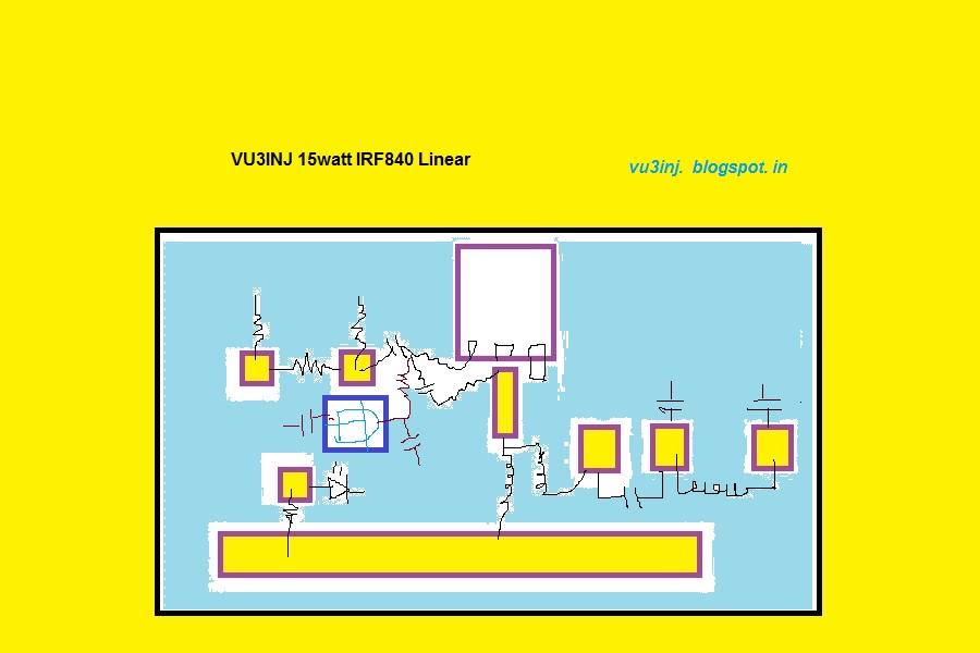 |
| 15watt linear component placement |
 |
| 15watt linear pad placement |
Descriptions, History :-
I had made this linear by accident. My 5watt cw tx/ DSB tx was not giving me signal reports. I was worried ! What is the problem ? Then it occurred to make a single device linear . One ckt was interesting . Put queries in the Indian Homebrewers forum at Facebook. And lots of reply came. VU2RON, VU2ESE, VU2DEV and lots more friend jumped in.
Finally tried it with IRF510 but it went burst with 25volt dc power supply. Then changed the IRF840/IRF640. Both worked fine. vu2ese had suggested me to put some 200pf at the drain. VU2DEV suggested making a Pi-LC matching. He even pointed out the calculations in the ARRL handbook , which he had gifted me. But, I settled for transformer & toroids. Ron hinted on impedance transformation of this broad band transformer.
Then made it. I used Small pig nose baluns bought from tpsonline Bhopal. Put 6 togather. 3x2, Glued with water pipe glue and it worked. It did not heat-up. The biggest problem with the ferrite is that it heats up and freq response depending on the size and material. So, we have to take care of this problem.
I used in the input a resistive 3db pad. This db-pad solved my problem for loading the exciter, proper match etc. It was happy happy solutions. With pad some fraction of input power is wasted in heat. Its okey.
I put LED to indicate power supply presence. I put a protective diode 1N4007. Not shown here. The VCC line is a big one. Instead of deriving 12volt from the pcb I used the LM7805 voltage regulator. The simple preset is used on the pcb to bias the gate of IRF. At gate a small value resistor 5 ohm is used to stop parasitics. If you have ferrite bead please use that also. Now, a days we don't find ferrite bead esily.
Filter is classic bilateral 50 ohm three pole. Simplicity. Actually 7 pole filter should be used for more spectral purity.
The relays for changing over the antenna etc are not used here as it was meant to be a beacon / CW tx.
Components & Schematics:-
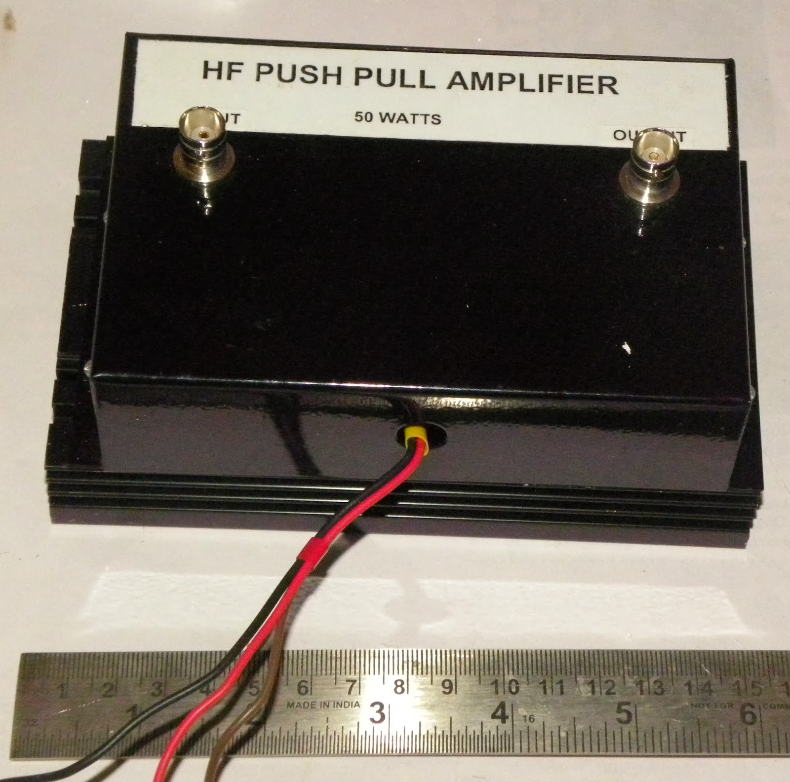
 |
| vu3inj linear |
Setting up the linear:-
this requires some care & instruments.
Put Digital Multimeter into 10A range. Set the current to about 100mili amp. Now key the exciter. Make sure there is RF. This will increase the linear current to about 1.2 Amp. Use the dummy load or dipole antenna. VU2PTR digital VSWR meter will indicate the 15watt. So, this is the set-up. Nothing more. Mind you the preset tuning is little trickey. Slight increase in the bias and power jumps from 5 watt to 15watt. At one point of time you will feel that heatsink is too much hot but there is no power increase. buck down a little... don't set it for constant 1 amp. at max 300ma is also good. Do little experiments but just care for heat....
This linear has been never tested on SSB. If I ever do, will let you know.My approach was use whatever is on hand. Till date I have made two linears and both work wonderfully. One is with me and one is with VU2TOO.
Heat sink:-
It is one of the most important factor in this linear. You ought to use a biggest heatsink you can find. Old CPU heasink is okey. I also use the fan.
On Air test:-
On one two occasion I asked for listening service from VU3INK now (VU2JYX ), VU2DEV and two more hams. I am thankful to you Kishore for being with me. My signal was good. consistently 55 to 57. In this I had not tuned my antenna at all. SWR was around 2.5, So, the signal reports are not bad.
Will update few more fotos of linears and corrections within two days.

That's it folks the wheel has been re-invented.
Use it and don't forget to customize the bells and whistles ( relays, heatsink , box etc)