Friday, October 18, 2013

DDS VFO by VU2UPX, J1 and J2 connectors

Description: 16mm Plastic Shaft Rotary Encoder with 10mA Maximum Operating Current for Welding Machine


Hi

Just to point out how you need to connect the Rotary Encoder and the 2 switches to make your DDS frequency synth to work

The Rotary encoder connects at J1 connector marked on the PCB. Pin#1 of J1 connects to GND and Pin#4 of the same connector connects to VCC (+5V). Pin#2/3 connect to the data pins.

In the figure shown below the Centre Pin is the GND/Common Pin and the other two pins go to the Data pin on the PCB. These type of connectors also have a inbuilt Push/Press switch, but right now we are not taking that into account , in our project.

So you can simply consider that the centre pin is #2 and the other two pins are 1/3.


This is the schematic Diagram of the Rotary Encoder + switch and the Pull-up resistors connected to the Data pins. As you can see that the Centre pin #2 is connected to GND (Pin@1/J1) and Pin#1/3 Connected to data pins , Pin#2/3 on J1. Vcc is obviously connected to the combined junction of the two pull-up resistors shown in the schematic diagram. The Back side two switch points are left NC (Not Connected).

There are two more switches that need to be connected to the project at J2 and the same philosophy applies. Pin#1@J2 is GND and Pin#4@J2 is VCC (+5V). Pin#2/3@J2 are the datapins which connect to the Switch with Pull ups.


These switches are used to jump between Frequency step size. Experiment to find out how this functions.

In short you will have to assemble these things separately on a vero board. My friend Ravi has assembled this thing on a Vero Board and maybe he can support my explanation with some photographs (Top/Bottom).

Hope you are now able to understand how to get the kit to work and hope to see your successful experimentation on the Blog.
 Regards
Charudatt

Please Note:-
It is explained very thoroughly, i can not think of writing it more beautifully, so am reproducing the mail as it is.Thanks, De vu3inj, indrajitsinh
Those who require PCB and programmed PIC please contact Ravi Miranda https://www.facebook.com/groups/Indian.Homebrewers/

Thursday, October 17, 2013

DDS VFO by VU2UPX


The circuit is in three parts. One is DDS Controller board consisting of the AD9850 and PIC.Second board consist of LCD display 16*2 , I have used chines JHD 162A. Third part is the Rotary Encoder and Swithes and the Flexible ribbon connector between the two modules.

A little story of mine.:- I had bought two DDS AD9850 modules from ebay (Om Priyashlok Arya). Then i was searching for the controller. Tried few known sources. But, there was some sort of problems like the genunie PIC was not available ,There was problem in programming. Another ham did not respond to my request. I had tried all the known sources. Some said you have to wait
 The DDS VFO
This is the original design by the VU2UPX himself. On my recent visit to the mumbai by chance i met the vu2upx and he promised to help, gave me PCB and programmed IC.  It turned out that his design approch was very different and genuine so that i could not search/find the ckt on google. Finally i gave up and sought his help in making this DDS VFO. I am in process of finally running and will update the information ASAP.

My request:- vu2upx is a very busy person. Friendsplease, if you have any query , questions please put it on facebook group and usually he responds within one or two days. thanks.

Tuesday, October 8, 2013

TA7358AP

I have fallen in love with this IC. It is cheap, easily available and usable to make a Mixer, DSB modulator, Demodulator and on first try it works. I have bought it from Raj Kamal Electronics , Lamington Market, Mumbai for Rs35/- a piece on bulk purchase.

From the datasheet i had predicted that it might be useful to me but never tried one. First i bought it about  morethen 15 years ago. I could not test it. B ut in 2011 i got a chance to work on it.

From it now i make a Direct Conversion receiver. 7058kc DSB modulator using the cheap 11059kc and 4000kc xtals. It uses two 7358 ic and two oscillators. I have made one Premixed oscillator using single 7358 and two oscillators.

Once my scanner starts working will share the circuits. Also dont forget to visit the py2ohh.w2c.com.br web site it has wonderful resources and ideas.

Saturday, September 28, 2013

XTAL VFO


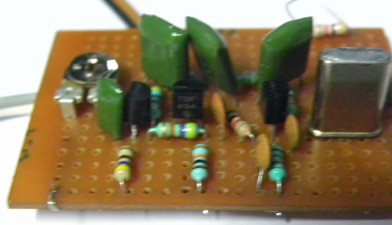
This XTAL oscilator was not showing the greater shift. Crystals used was hc69 full size but shift was only 400hz . Very poor shift. I wanted freq shift of few kHz. During reading Internet and practical experience with these Chinese half size xtals, I noticed, that osc requires that feed back capacitance should be low. Earlier I was using 1000pf, 1000pf (c1,c2).So, I replaced them with 100/180 PF. This was the value available with me, nothing particular about it. It clearly showed the shift of one kHz. This shift is good fore CW receiver and transmitter. Body of XTAL metal-can was grounded so due to hand capacitance seen no variations in freq.

     Q1 is bc547, Q2 BF494b and Q3 bc547. It is powered from regulated 12v DC but i generally use 5vdc as source. This gives me enough RF to drive mixers, etc.


Thursday, September 19, 2013

vwn transmitter, Tx


vwn 40 meter tx, (second build)
Earlier i had built the vwn tx. it showed good strength on air but somehow it was not showing the tuning up characteristic as given in the literature of the vwn tx.

Then i made this second transmitter. On dummy load and frequncy counter it shows good heat generations and accurate frequency 7058kc but, one of the days i  promised this tx to my friend so putting it on the box and hope it works for him, in atleast AM/CW mode. He likes the cw. Hope this will fill up his logbook.
In the first transmitter there was problem due to the tank- which is a very vital element of this transmitter. I have (as of Jan2014) an LC meter and can verify the design L value and actual L value. Progressing. I will hand over this tx with the request to make the contacts and antenna tune up.

19 Aug 2015 :-
This has given me good signal for my testing the receivers antennas but as of July 2015 I have gifted it to one new ham.. Hope he operates it beautifully. on 7058kc. I will miss it. It was one of the well built vwn.

vwn transmitter, VFO & AM modulations scheme


Tuesday, September 17, 2013

EL84 TX, 80 Meter, 3.579 Xtal


An EL84 single tube CW/AM Transmitter

 
Introduction: Bring back the nostalgia with this one tube transmitter. The EL84 tube is still available or can be salvaged from an old radio set. New tubes can be ordered from http://thetubestore.com.
The circuit is self-explainatory and should always be used with proper output load. The transmitter takes about 10W DC in and puts about 5-7W out.
Construction: Mount the nine pin tube socket on the general purpose board by 1/2" spacers at one end of the board. Keep all lead lengths as short as possible to avoid losses and parasitic. All resistors should be 1/2W unless stated on the schematic. The tuning capacitor on the tank circuit is air variable type. Do not use the common 2J type broadcast receiver gang condenser. Keep the connecting lead to the tuning condenser short and thick. Use 35mm film container to wind the tank coil. For link winding use hookup wire for easy winding. Tape the entire assembly for neatness. Mount the tank coil  close to the output circuit without using long connecting leads.
Tuning: After applying power, give about 30 seconds for the tube to warm up. Connect a 6V 0.5 Amp lamp as dummy load and press the key. If Murphy did not visit you, the lamp should light up indicating RF. Tune the 150pf condenser for maximum output, i.e. maximum brightness of the lamp. At full power the lamp will glow ultra bright. I recommend use of antenna tuner on air.
 
Note. For AM transmission the code key can be used as PTT. Close key to transmit.

CAUTION – High voltages are present in the circuit, which could be fatal. Please take all precautions. Always use a fuse protected power cord. Make sure the grounding is proper.


Acknowledgement: I'm thankful to the following HAMs for their valuable advices on this circuit - Harry Lythall (SM0VPO), Hans Summer (G0UPL), Niel Wiegand (W0VLZ), Stan Wilson (AK0B), John Kukla (KB10JM), Ivica Bogdanovic (YU1QRP) and SWL Anatoly Lisowsky, David (M0DAD), M Reeves (AB5L)