Showing posts with label AD9850. Show all posts

Sunday, February 9, 2014

DDS VFO CKT

This is part-2


5volts and 3.6 volt power supply for ebay module
all diodes are 1N4007, C1 and C2 are 100mfd,25volt electolytic capacitor. voltage regulator is LM7805.
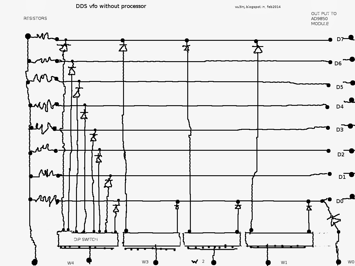
 diode matrix there are 32 plus 1 diodes. one end of dip switch is connect and goes to the counter ic. please note that on the resistor where diode joins it is indicated by dots.
resistors are 68k, all diodes are 1n4148
four dip switch. DIP switch has 8 on/off individual switch in miniature.
I have soldered the 16pin ic pad and on that mounted the dip switch.
All the diodes are connected with dip switch as shown on the w4 . For the clarities sake i have not drawn the other diodes.

low fequency oscillator and counter for driving the diode matrix and putting the word into the dds vfo ad9850.

74hc04 is gate. 74hc4017 is a counter ic.


Interconnections of this modules.


work is in progess and there is still some glitches. i am little strained at present and hope to redo this module in future.( what i mean by glitch, setting of freq is not perfect, low freq osc is wobbling changing its own freq and thus effecting the modules output freq.....)
please note:-  
It is tiresome to work on simple vero board, if you want to try please make a proper pcb.

it has the limitations also,
its a fixed frequency type.
you have to tweak a little to run it on your exact desired frequency.
buffer after the ebay module is needed.
some sort of shielding for rf is needed.

but, with this ckt you will be able to test your bunch of ebay modules.... so, it does not replace any pic, processor based ckt but it complements and where beacon is to be run or only wants to be on afixed freq  this is a good and cheap options,


IT DOES NOT WORK

AS OF 06 MARCH 2014 .

Anyone wants to try please let me known your outcome, so i also change my ckt accordingly and thank you.

This is second part the PREVIOUS ARTICLE IS http://vu3inj.blogspot.in/2014/01/dds-vfo.html

Thursday, October 17, 2013

DDS VFO by VU2UPX


The circuit is in three parts. One is DDS Controller board consisting of the AD9850 and PIC.Second board consist of LCD display 16*2 , I have used chines JHD 162A. Third part is the Rotary Encoder and Swithes and the Flexible ribbon connector between the two modules.

A little story of mine.:- I had bought two DDS AD9850 modules from ebay (Om Priyashlok Arya). Then i was searching for the controller. Tried few known sources. But, there was some sort of problems like the genunie PIC was not available ,There was problem in programming. Another ham did not respond to my request. I had tried all the known sources. Some said you have to wait
 The DDS VFO
This is the original design by the VU2UPX himself. On my recent visit to the mumbai by chance i met the vu2upx and he promised to help, gave me PCB and programmed IC.  It turned out that his design approch was very different and genuine so that i could not search/find the ckt on google. Finally i gave up and sought his help in making this DDS VFO. I am in process of finally running and will update the information ASAP.

My request:- vu2upx is a very busy person. Friendsplease, if you have any query , questions please put it on facebook group and usually he responds within one or two days. thanks.