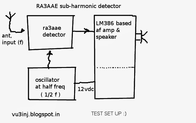
Few days ago a friend asked me about the simple receiver to practise his CW Skills. Well, i have done few experiement with poliakov receiver and they have given a repeatable , proven results. I scanned indian products and could not find any thing for the small kids, new hams or something very basic minimalist, cheap devise. So, I filled in the space. Its better than pixie, tixies, foxx etc but less than well made DC receiver . Brainstorming started, I thought let's re-re-invent the wheel.....
here is the result
This requires minimum of time to make and its up and running within hours. It can be used to practise morse on air. It will certainly not bring the good dx nor it is frequency flexible.
See my previous posts, you will find many experients on this subharmonics receiver. It is still in development stage. You can have dip file from me. Just drop an email. I am making a suitable transmitter. In my mind is two way. One to use this LO and then use the doublers amplifiers to arrive at 40 meter so the hard to find find 7159kc xtal can be avoided and further 3560kc resonator can be used to give flexibility of freq. working on it. Tx might be three stage 3watt, along with relay change over etc. Another tx will be using 7159kc xtal , class e two stage to arrive at 3watt.
 Lets begin::: It all began with this ckt, have a good look. From this all other things are derived. First transistor is an RF amplifier. Two back to back diodes forms the sub-harmonics mixers. Second transistor is AF amplifier. The gain of This AF/RF amp depends on Rc/ Rb. If you find the gain is little low try experimenting with it. 470k/4k7 will give gain of 100. The choice of transistor will determine the gain as well as noise. The RF transistor should have high ft ( gain bandwith product) that way it will produce good signal. In my experiments I found that bc547c, bc547b gave different gain.
Small whip antenna works fine. For higher frequency please use some broad band transformer coupled RF amp. That will give good result in 20 meter. At present this ckt is good enough for 40 meter.
The diptrace schematics screen shot.
 |
This is the diptrace pcb making software , This time I took time to make the schematics on this. EArliers I used make by hand and then scan. I realized to make a professional grade pcb, good quality image and parts making the pcb software is a must.
The ckt diagram

List of components
40 METER BAND RECEIVER
# RefDes Value
1 A1 whip antenna
2 C1
3 C2 100p
4 C3 100n
5 C4
6 C5 100n
7 C6 10 mfd
8 C7 10 mfd
9 C8 100p
10 C9 100p
11 C10 100p
12 C11 100n
13 C12 100 mfd
14 C13 1000 mfd
15 C14 33p
16 C15 10 mfd
17 C16
18 C17 100 mfd
19 C18 100 mfd
20 C19
21 C21 100n
22 D1 green LED
23 D2 1n4148
24 D3 1n4148
25 D4 1n4007
26 J1 speaker out put JACKPIN
27 J2 dc input JACKPIN
28 L2
29 L3
1 A1 whip antenna
2 C1
3 C2 100p
4 C3 100n
5 C4
6 C5 100n
7 C6 10 mfd
8 C7 10 mfd
9 C8 100p
10 C9 100p
11 C10 100p
12 C11 100n
13 C12 100 mfd
14 C13 1000 mfd
15 C14 33p
16 C15 10 mfd
17 C16
18 C17 100 mfd
19 C18 100 mfd
20 C19
21 C21 100n
22 D1 green LED
23 D2 1n4148
24 D3 1n4148
25 D4 1n4007
26 J1 speaker out put JACKPIN
27 J2 dc input JACKPIN
28 L2
29 L3
34 Q1 BC549C rf AMP
35 Q2 BC547B af amp
36 Q3 BC547B Oscillator
37 R1 470k
38 R2 4k7
39 R3 470 ohm
40 R4 2K2
41 R5 120k
42 R6 2k2
43 R7 100 ohm
44 R8 120k
45 R9 2k7
46 R10 100 ohm
47 R11 47k
48 R12 470
49 R13 10 ohm
50 R14
51 T1
52 T2
53 U1 7805
54 U3 1/2 TDA2822m
55 Y1 3579kc
56 Y2 3579kc
35 Q2 BC547B af amp
36 Q3 BC547B Oscillator
37 R1 470k
38 R2 4k7
39 R3 470 ohm
40 R4 2K2
41 R5 120k
42 R6 2k2
43 R7 100 ohm
44 R8 120k
45 R9 2k7
46 R10 100 ohm
47 R11 47k
48 R12 470
49 R13 10 ohm
50 R14
51 T1
52 T2
53 U1 7805
54 U3 1/2 TDA2822m
55 Y1 3579kc
56 Y2 3579kc
Note of TDA2822m,
I always used LM386 but somehow I am finding difficult to get a good chip. All Chinese chips are faulty. So, tried TDA2822m an 8 pin DIP ic. It is good one. It contains two amplifiers. This IC is a low voltage, low power AF amp. So, use 4 to 5 volt maximum. When used with 12volt supply it starts heating up To reduce heating on IC, I used a ballast resistor of 200 ohm ( 100 ohm 2watt + 100 ohm 2watt) , so it stopped heating up. Remember this thing. Only one part out of two is used.
Note on Antenna.
For making pcb from schematics , I put a two tank band pass filter, otherwise single tank with whip antenna is sufficient for all purpose.
Note on the Xtal Oscialltor- 3579kc
we need very small Rf injection to the diodes so single transitor osc is used. There is shown two coils and two xtals. I put it there only reason if someone wants to modify experiment , the same pcb will be useful. F6GQB. So, I can get 60k shift , more than enough for this set-up. Except this two square I have not hidden anything. Only this squares have few extra empty parts. Only single xtal is used, No RFC used.
If anything is missing please let me know.
You can make it, but remember its still in development stage. When I first put it on facebook there was two errors. one transistor part was wrongly labeled. And 12 volt and 5volt lines mixed up at 2822m. So, ckt on this blog should be final.
THE RECEIVER CKT IS FINAL. there will be no modifications. but revision of write-up , addendum will be added later on.
Input Band Pass Filter modifications. As of 17 may 2016 Modified the input filter system. Put fixed inductor 2.2 micro hentry with 215 pf =( 100p || 100p) + 180pf , tap taken from junction of both 100pf. The RFC of 2.2 micro henry can be used ready made or made one 9 to 10 milli-meter dia plastic tube, I used felt pen, 30swg around 22 to 24 turns close wound, length will be 10 to 12 milli-meter. Measure it with LC meter. Plastic tubing former was around 3 cm long. Will upload close-up fotos soon.
Receiver sounds good. Housed in the home made box. Other modifications like painting, putting nut-bolts that will happen as per need but electrical ckt is finale. Am breakthrough is very minimal. AF filter might be a good idea. But the simplicity beats all. Make this receiver and please wait for compatible transmitter.
so, till then enjoy, the wheel has been re-re-invented, take a ride.
de vu3inj.
here is a link to my youtube chanel. on similar design made the 20 meter one. have a look at https://www.youtube.com/watch?v=G4LTTf-waVc please
NB;- you may write down few words please.
THE RECEIVER CKT IS FINAL. there will be no modifications. but revision of write-up , addendum will be added later on.
Input Band Pass Filter modifications. As of 17 may 2016 Modified the input filter system. Put fixed inductor 2.2 micro hentry with 215 pf =( 100p || 100p) + 180pf , tap taken from junction of both 100pf. The RFC of 2.2 micro henry can be used ready made or made one 9 to 10 milli-meter dia plastic tube, I used felt pen, 30swg around 22 to 24 turns close wound, length will be 10 to 12 milli-meter. Measure it with LC meter. Plastic tubing former was around 3 cm long. Will upload close-up fotos soon.
Receiver sounds good. Housed in the home made box. Other modifications like painting, putting nut-bolts that will happen as per need but electrical ckt is finale. Am breakthrough is very minimal. AF filter might be a good idea. But the simplicity beats all. Make this receiver and please wait for compatible transmitter.
 |
| BPF |
de vu3inj.
here is a link to my youtube chanel. on similar design made the 20 meter one. have a look at https://www.youtube.com/watch?v=G4LTTf-waVc please
NB;- you may write down few words please.